
Soft Start For Torch - Increases The Life Of Torch Bulbs

The modification of flashlights to extend the lifespan of halogen or krypton bulbs represents a practical approach to improving efficiency and cost-effectiveness. By utilizing a MOSFET in conjunction with a resistor, the circuit effectively mitigates the high inrush current that typically occurs when the flashlight is powered on. The choice of the BUZ11 or BUZ10 transistors is particularly advantageous due to their robustness and ability to handle the necessary current without overheating.
The circuit design is straightforward, requiring minimal components while ensuring that the flashlight operates reliably. The integration of a gate resistor serves to slow the charging of the gate capacitance, thereby controlling the turn-on speed of the MOSFET. This controlled turn-on reduces the likelihood of filament burn-out, extending bulb life significantly.
In practical implementation, careful attention must be given to the physical layout of the components within the flashlight housing. Space constraints may necessitate the use of surface-mount resistors, which can be soldered directly onto the existing circuit board or switch terminals. This approach not only conserves space but also maintains the integrity of the flashlight's design.
Additionally, the modification may alter the user experience by reversing the polarity of the battery installation and the switch operation. Users should be informed of these changes to prevent confusion. Overall, this modification enhances the longevity of the flashlight while providing a cost-effective solution to the inherent limitations of incandescent bulbs.The halogen or krypton bulbs in modern torches (USA and Canada: flashlights) have a limited life and are not particularly cheap. A simple modification in the torch lengthens the life appreciably. It is a fact of nature that any incandescent bulb has anite life. However, the bulbs in modern torches (US and Canada:‚ashlight) have a less-than- average life. The reason for this is that the halogen or krypton bulbs used are operated at over-voltage to give as bright a light as feasible. The life of these bulbs may be extended simply by connecting a resistor in series with the bulb. For instance, when the battery voltage is 6V and the bulb is a 500mA type, a series resistor of 1 will reduce the voltage across the bulb by about 0.
5V. This will certainly lengthen the life of the bulb, but it will also cause a reduction in the available brightness. Also, energy is wasted in the resistor (evinced by heat production). Clearly, this is not a very good solution to the problem. A better one is shunting the bulb with a transistor in series with a resistor. Another well-known fact is that incandescent bulbs normally burn out when they are being switched on.
This is because the resistance of the cold filament is significantly lower than that during normal operation. This results in a switch-on current that is much higher than the normal operating current. Clearly, much is to be gained by damping the switch-on current. The switch-on current may be limited by a simple circuit that is small enough to allow it to be built into most types of torch.
As the diagram shows, such a circuit consists of nothing more than a metal-on-silicon-field-effect-transistor, or MOSFET, and a resistor. The transistor may be almost any current n-channel type that can handle the requisite power. The popular BUZ11 or BUZ10 is eminently suitable for the present application. The requisite limiting of the start-up current is provided by the internal gate capacitance of the transistor in conjunction with the large gate resistor.
If needed, a small capacitor may be added between gate and drain. Once the transistor is conducting hard, the remaining losses are negligible. This is true also when the torch is switched off: the quiescent current‚owing through the transistor is much smaller than that caused by the self-discharge of the batteries. Since it is much simpler to break into the positive supply line of a torch than into the negative line, the addition of the limiting circuit makes it necessary for the batteries to be inserted into the torch the other way around from normal (as indicated by the manufacturer).
Also, the on/off switch of a modified torch works the other way around from normal. Fitting the modification in some of the popular Mag-Lite torches is fairly straightforward. After the rubber cover of the on/off switch has been removed, the entire push-button switch mechanism may be removed by releasing a central hexagonal bolt. The switch terminals may serve as soldering supports for the transistor-resistor series network. If it proves impossible to obtain a 47 M resistor, four or five surfacemount-technology (SMT) resistors of 10 M may be linked in series.
Such a link works just as well and is almost as small as a normal 47M resistor. 🔗 External reference
Related Circuits
A simple soft start circuit is being developed that initially routes power through a resistor or thermistor before activating the main load. The soft start circuit is designed to gradually increase the power supplied to a load, thereby minimizing inrush...
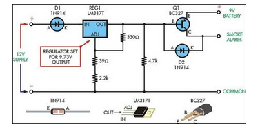
Although smoke alarms are relatively inexpensive devices, the cost of 9V batteries can quickly surpass their initial purchase price. Additionally, the annoyance of random beeping can be a significant drawback. Smoke alarms are essential safety devices designed to detect smoke...

The circuit depicted in Figure 3-49 illustrates an autotransformer that is controlled by a time relay (KT). The delay time set by the KT relay corresponds to the motor's startup duration. The circuit utilizes an autotransformer, which is a type...
Two soft start power supplies. The output voltage slowly increases to the desired output The circuit comprises two separate soft start power supply modules designed to gradually ramp up the output voltage to a predetermined level, thereby minimizing inrush current...
The delay time for all circuits shown has been revised. The optimum is around 100ms - sufficient for around 5 full cycles at 50Hz, or 6 cycles at 60Hz. It is also quite alright to run the transformer to...
McCAD E.D.S software, a complete family of integrated electronic designs systems for MS Windows and Macintosh OS platforms. McCAD Electronic Design Systems offer a choice of design environments with a wide range of system configurations tailored to the specific...