
solar charger picaxe

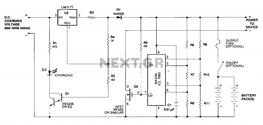
The PICAXE solar panel battery charge controller is designed to manage the charging process of batteries using solar energy. This system typically involves several key components: the solar panel, battery, PICAXE microcontroller, and various electronic components such as resistors, diodes, capacitors, and possibly a voltage regulator.
The solar panel converts sunlight into electrical energy, which is then directed to the charge controller. The PICAXE microcontroller is programmed to monitor the voltage levels of the solar panel and battery, ensuring that the battery is charged efficiently without overcharging. The programming of the PICAXE involves writing a code that dictates how the microcontroller responds to different voltage levels, controlling the flow of current to the battery.
In terms of circuit design, the solar panel is connected to the input of the charge controller. A diode is often included in the circuit to prevent reverse current flow from the battery back to the solar panel during low light conditions. The output of the charge controller connects to the battery, which stores the energy for later use.
Additional components may include a voltage divider to measure the battery voltage accurately, and potentially a display or LED indicators to show the charging status. The entire system can be housed in a protective enclosure to safeguard against environmental factors.
The programming of the PICAXE can include features such as temperature compensation, where the charging parameters adjust based on the battery temperature, and load control, which can disconnect the load if the battery voltage drops below a certain threshold. This ensures the longevity of the battery and optimizes the charging process, making the system efficient and reliable for renewable energy applications.Construction and programming PICAXE solar panel battery charge controller.. 🔗 External reference
Related Circuits
This project involves a mini USB car charger circuit that is simple to construct using only three components. The core of the circuit is the LM78M05 integrated circuit (IC), which is a 5V positive voltage regulator. This IC includes...

Create a robotic team mascot for a workplace. The initial phase of this project involved designing a charger for the robot's batteries. The aim was to develop a charger compatible with various NiMH battery packs ranging from 700 mAh...
Schematic and description of a simple and easy-to-build NiCd and NiMH battery charger circuit that is capable of charging multiple NiCd and NiMH batteries. The circuit for the NiCd and NiMH battery charger is designed to be straightforward, allowing for...

12 Volt Gel Cell Charger. Recently, an amateur was looking for a gel cell charger that would first charge at a fixed rate and then later switch to a trickle charge when the cell was fully charged. After reviewing...
Charging is achieved using a constant current of 60 mA for AA cells, reaching a cutoff voltage of 2.4 V per cell, at which point the charging process must be terminated. The charging system is designed for multi-cell battery...

This is a simple and low-cost NiCd and NiMH battery charger. The schematic diagram indicates that the charging current (I) should be set to 1/10 of the battery's rated capacity. For instance, if the battery has a rated capacity...