
xenon strobe circuit

Xenon lamps are high-intensity discharge lamps that emit a bright flash of light when an electric current passes through the xenon gas contained within the lamp. These lamps are commonly used in strobe light applications, photo flash units, and various signaling devices due to their ability to produce intense and brief bursts of light.
A typical xenon strobe circuit consists of several key components, including a power supply, a triggering mechanism, and the xenon lamp itself. The power supply usually provides a high-voltage output, which is essential for ionizing the xenon gas and allowing current to flow through the lamp. This high voltage is typically generated using a capacitor that is charged to a specific voltage level before discharge.
The triggering mechanism is crucial in determining when the xenon lamp will emit a flash. This can be achieved using various methods, such as a simple switch, a phototransistor, or a more complex timing circuit. Once triggered, the stored energy in the capacitor is released, creating a rapid discharge of current through the xenon lamp, resulting in a bright flash of light.
In designing a xenon strobe circuit, it is important to consider the following parameters: the voltage rating of the capacitor, the resistance values in the circuit, and the specifications of the xenon lamp being used. Proper calculations should be performed to ensure that the circuit operates safely and effectively, avoiding excessive current that could damage the components.
Schematic diagrams for these circuits can be found in various electronics resources, and many are available for free use. These diagrams typically illustrate the arrangement of components, including the power supply, capacitor, triggering mechanism, and xenon lamp, allowing for easier construction and troubleshooting of the circuit.Xenon lamp, strobe light circuits, xenon strobe, photo flash, photoflash,schematics or diagrams, all free to use. My inspiration came from a strobe circuit that was in a school fire alarm.. 🔗 External reference
Related Circuits
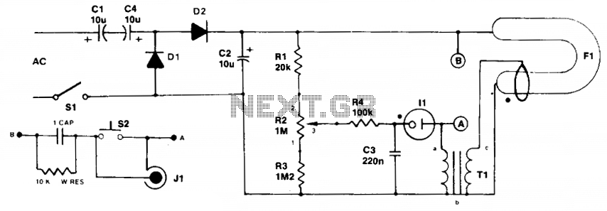
Initially, the neon and xenon lamps do not conduct and behave like very high (almost infinite) resistance. Capacitors C1 and C4, in conjunction with diodes D1 and D2, form a voltage doubler circuit, allowing C2 to charge up to...
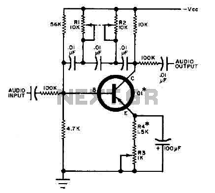
This circuit is designed for selective tuning adjustments between two closely spaced audio tones. The frequency of the circuit is determined by the selected capacitors and resistors in the feedback loop between the collector and base of transistor Q1....
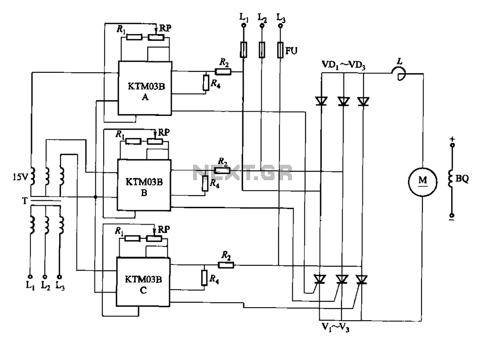
Adjusting the phase potentiometer RP can change the conduction angle of each corresponding thyristor (V1-V). This adjustment alters the voltage applied across the load. The circuit utilizes a phase control technique to manage the power delivered to a load by...
This electronic lie detector circuit project will provide two readings: one for challenging questions posed to the subject and another to indicate their emotional state. The electronic lie detector circuit operates on the principles of galvanic skin response (GSR) and...

The objective of the circuit is to create an electronic dice using the functionality of a 555 timer integrated circuit operating in astable mode. The electronic dice circuit utilizes a 555 timer configured in astable mode to generate a series...

This pulse generator produces square pulses ranging from 1Hz to 100KHz with an adjustable pulse width of nearly 0-100%. It operates on a voltage of 5-15V, making it suitable for both TTL and CMOS circuits. This device is essential...