
Soldering Iron Tip Preserver

This circuit utilizes two 555 timer ICs to manage the heating and standby operation of a soldering iron effectively. The first timer (IC1) is configured in monostable mode, which allows it to trigger a warm-up sequence for the soldering iron. Upon activation, IC1 provides a high output for a predetermined duration, ensuring that the soldering iron reaches its optimal operating temperature efficiently. The second timer (IC2), configured in astable mode, takes over once the warm-up period is completed. IC2 generates a pulse width modulation (PWM) signal that controls relay RLY1, which in turn regulates the power supplied to the soldering iron.
The relay acts as a switch that connects or disconnects the power to the soldering iron based on the output from IC2. The PWM control helps maintain the soldering iron at a lower standby temperature, reducing oxidation and prolonging the life of the soldering tip. The detection mechanism for the soldering iron's presence is critical; it relies on a simple electrical contact that indicates when the iron is placed back in its stand. This ensures that the standby temperature is only maintained when the iron is not in use.
Furthermore, the circuit's design allows for flexibility. The warm-up time and standby temperature can be fine-tuned by adjusting the resistor values in the circuit. This adaptability makes it suitable for various soldering iron models, provided that the power supply requirements are met. Overall, this circuit enhances the efficiency and usability of soldering operations, making it a valuable tool for electronics engineers and hobbyists alike.Although 60/40 solder melts at about 200°C, the tip temperature of a soldering iron should be at about 370°C. This is necessary to make a good quick joint, without the risk of overheating delicate components because the iron has to be kept on the joint for too long.
Unfortunately, at this temperature, the tip oxidises rapidly and needs const ant cleaning. That`s where this circuit can help - it keeps the soldering tip to just below 200°C while the iron is at rest. Oxidisation is then negligible and the iron can be brought back up to soldering temperature in just a few seconds when needed.
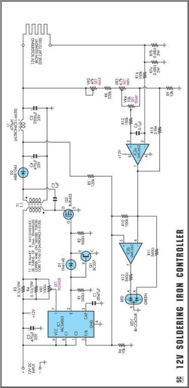
In addition, normal soldering operation, where the iron is returned to rest only momentarily, is unaffected because of the thermal inertia of the iron. Two 555 timers (IC1 & IC2) form the heart of the circuit. IC1 is wired as a monostable and provides an initial warm-up time of about 45 seconds to bring the iron up to temperature.
At the end of this period, its pin 3 output switches high and IC2 (which is wired in astable configuration) switches the iron on - via relay RLY1 - for about one second in six to maintain the standby temperature. The presence of the iron in its stand is sensed by electrical contact between the two and some slight modification of the stand may be necessary to achieve this.
When the iron is at rest, Q1`s base is pulled low and so Q1 is off. Conversely, when the iron is out of its stand, Q1 turns on and pulls pins 2 & 6 of IC2 high, to inhibit its operation. During this time, pin 3 of IC2 is low and so the iron is continuously powered via RLY1`s normally closed (NC) contacts.
Note that the particular soldering iron that the circuit was designed for has its own 24V supply transformer. Other irons may need different power supply arrangements. The warm-up time and standby temperature can be varied by altering R2 and R5, as necessary. 🔗 External reference
Related Circuits
It still uses a transistor to do some switching, and it still needs a pair of diodes and capacitors, as would be used in a conventional multiplier, but it doesn't require a steady stream of pulses and the output...
One reason why commercial soldering stations are expensive is that they typically require soldering irons with built-in temperature sensors. Commercial soldering stations are designed to provide precise temperature control and consistency during soldering operations, which is essential for achieving reliable...
This Project Multi-Pattern Running light is used to generate several designs of Running Lights. We use ten LEDs for display. The designs can be selected by using two switches UP and DOWN. The 8 bit Microcontroller is used to...
Processor-based systems typically require a voltage supervisor chip to generate a clean reset pulse for the processor whenever a brown-out condition in the power supply is detected. More complex designs that utilize multiple power supplies can become unreliable if...
SigmaTel's STAC9721 and STAC9723 are general-purpose 18-bit stereo, full-duplex audio CODECs that adhere to the AC'97 (Audio Codec 97 Component Specification Rev. 2.1) specifications. These devices utilize SigmaTel's proprietary Sigma-Delta technology to achieve a DAC signal-to-noise ratio (SNR) exceeding...
The circuit was designed to create an audio mixer that can be assembled in modules while providing 6 or more input channels. An audio mixer is a device used to combine multiple audio signals into a single output. The audio...