
Multipattern Running LEDs

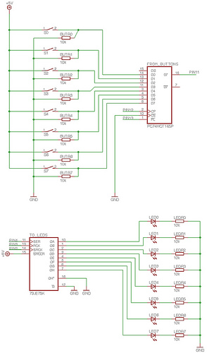
The described project features a Multi-Pattern Running Light circuit that employs a microcontroller to control the operation of ten light-emitting diodes (LEDs). The system is designed to allow users to select different light patterns using two switches labeled UP and DOWN. The core component of this circuit is the AT89C2051, an 8-bit microcontroller that manages the overall functionality.
The microcontroller interfaces with the LEDs through its output ports, enabling it to switch the LEDs on and off based on the programmed patterns. Each LED can be controlled individually or in groups to create various visual effects. The UP and DOWN switches provide a simple user interface for pattern selection, allowing for intuitive operation.
Power for the circuit is supplied via a step-down transformer, ensuring that the microcontroller and LEDs receive the appropriate voltage levels for optimal performance. The design may also include current-limiting resistors for the LEDs to prevent excessive current flow, which could damage the components.
In terms of operation, the microcontroller continuously polls the state of the UP and DOWN switches. When a switch is activated, the microcontroller updates the current LED pattern accordingly. The program logic within the microcontroller dictates how the LED patterns change in response to user input, cycling through predefined sequences or effects based on the selected pattern.
This project exemplifies the integration of microcontroller technology in creating dynamic lighting systems, showcasing both hardware and software design principles in embedded systems.This Project Multi-Pattern Running light is used to generate several designs of Running Lights. We use ten LEDs for display. The designs can be selected by using two switches UP and DOWN. The 8 bit Microcontroller is used to control all the operations. It control the LEDs though the Ports. The above system is monitored and controlled by the 8 bit microcontroller AT89C2051. The Microcontroller continuously monitors the Switches and switch on/off the LEDs according to the Program. The Power for the circuit is derived from the Step dow 🔗 External reference
Related Circuits
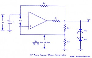
Non-sinusoidal waveform generators are also referred to as relaxation oscillators. The op-amp relaxation oscillator described is a square wave generator. Generally, square waves are relatively simple to produce. Similar to the UJT relaxation oscillator, the frequency of oscillation in...
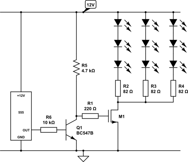
Create a circuit using a 555 timer to operate 72 LEDs simultaneously. A circuit has already been constructed, but there are concerns regarding its safety and longevity. A picture of the circuit is provided for review, and assistance is...
To enable the MonomeSerial software to recognize the monome clone, it is necessary to modify the Arduino's EEPROM serial number to match that of a genuine monome. Following Melka's updated instructions from the Bricktable blog is recommended. The D2XX...
This circuit converts the analog signal from the reversed LED, which is in sensing mode, and amplified by the operational amplifier, into a digital (on/off) signal. The original complex design has been simplified. An alternative approach is discussed in...
The following circuit illustrates a Dancing LEDs electronic circuit diagram. This circuit is based on the LM358 integrated circuit. Features: IC1A amplifies the signal. The Dancing LEDs circuit utilizes the LM358 operational amplifier to create a visually appealing light display....
This kit includes fully illustrated instructions and a circuit schematic. Components are adequately spaced for easy assembly and value identification on the board. The circuit board features silk-screened outlines for component placement, and the circuit pads on the solder...