
Square wave oscillator as wire tracer

The circuit described functions as a wire tracer, utilizing a square-wave signal generator to inject a modulated signal into the target wire. The square wave is characterized by its sharp transitions, leading to a rich harmonic content that extends across a range of frequencies. This property is crucial as it allows the signal to be detectable over varying distances and through various materials.
The essential components of the tracer circuit include a square-wave oscillator, which can be implemented using a 555 timer IC or a microcontroller programmed to output a square wave. The frequency of the square wave should be selected based on the application, typically ranging from 1 kHz to 10 kHz, to ensure adequate penetration and detection capability.
The output of the oscillator is connected to the wire to be traced, either directly or through a coupling capacitor to prevent DC offset. This allows the AC square wave to superimpose on the DC signal if present. The wire carrying the square wave will radiate electromagnetic energy due to the alternating current, which can be picked up by the nearby radio.
The radio, acting as a receiver, should be tuned to the frequency range of the square wave harmonics. When the radio is brought close to the wire, it will detect the oscillating field generated by the current within the wire, resulting in an audible buzzing sound. The intensity of the buzz will vary depending on the proximity to the wire and the strength of the injected signal.
This method provides a non-invasive means of tracing wires through walls or underground, allowing technicians to locate cables without the need for physical access. The simplicity of the circuit design and the effectiveness of the detection method make it a valuable tool in various electrical and telecommunications applications.The tracer works by placing a square-wave signal ?n the line to be traced, The square wave is full of harmonics. ? small radio placed close to a wire carrying this signal will buzz. The radi, therefore, is used as a probe to trace out the wire.
Related Circuits

A 555 timer configured as an astable multivibrator is used in this circuit to generate an audio note. The capacitance value can be changed to vary the audio note as desired. The circuit utilizes a 555 timer IC, which...
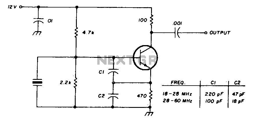
International Crystal OF-1 HI oscillator circuit for third-overtone crystals. The circuit does not require inductors. The International Crystal OF-1 HI oscillator circuit is specifically designed to operate with third-overtone crystals, which are capable of generating higher frequency oscillations compared to...

Oscillators that generate a predetermined number of pulses are often required in applications such as video work. This oscillator starts 13 ms after the control signal goes high and stops immediately when the input signal goes low. In electronic applications,...
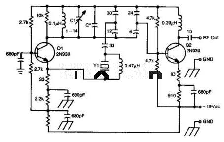
This oscillator circuit utilizes a 5th overtone crystal operating within the 85 to 106 MHz frequency range. The component Y1 represents the crystal. The circuit was initially designed for frequency control in a microwave oscillator. The oscillator circuit leveraging a...
A frequency reference for tuning up the RS-232 to 100 MHz RF desktop channel adapter elsewhere on this site, when I found this Saronix crystal oscillator in my junk box. A few minutes with AVRStudio produced an ATtiny12 to...
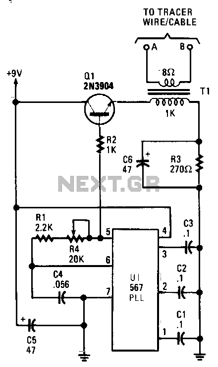
The tracer, which includes both a transmitter and receiver, is designed to trace a closed-loop wire or cable system. It follows the path of an induced voltage created by feeding a low-current, audio-frequency signal through the cable. When the...