
stable low frequency crystal

The Colpitts crystal oscillator is a type of electronic oscillator that uses a combination of capacitors and an inductor to create a resonant circuit, which is essential for generating a stable frequency output. The primary components of the circuit include the 2N3823 JFET, which serves as the active device, along with the crystal, which determines the oscillation frequency.
In this configuration, the crystal is connected in parallel with two capacitors, forming a voltage divider that influences the feedback necessary for oscillation. The JFET amplifies the signal, providing the necessary gain to sustain oscillations. The choice of the 2N3823 JFET is significant due to its low noise characteristics and high input impedance, which help maintain the stability and performance of the oscillator across varying temperature conditions.
The circuit typically requires a DC power supply to operate, and the output can be taken from the drain of the JFET. Additionally, the design may include biasing resistors to set the operating point of the JFET, ensuring that it operates in the appropriate region of its transfer characteristic for optimal performance.
The Colpitts oscillator is widely used in applications such as RF signal generation, clock generation for digital circuits, and in various communication systems where stable frequency generation is crucial. The design's simplicity and effectiveness make it a popular choice among engineers and hobbyists alike.This is the design circuit for a Colpitts-crystal oscillator circuit. It is suitable for low frequency crystal oscillator circuits. Using the 2N3823 JFET, this circuit has excellent stability because the temperature will not vary the 2N3823 JFET circuit loading. This is the figure of the circuit. 🔗 External reference
Related Circuits
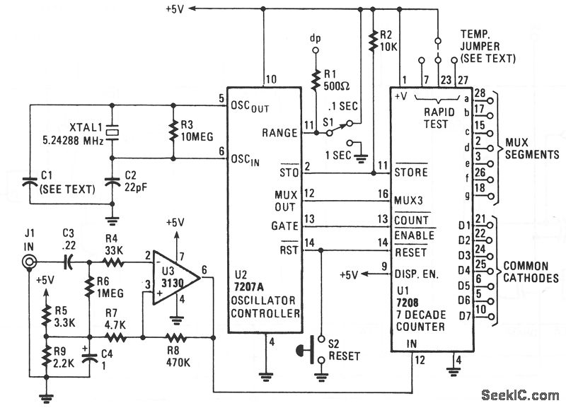
The circuit comprises an ICM7208 seven-decade counter (U1), an ICM7207A oscillator controller (U2), and a CA3130 biFET operational amplifier (U3). IC U1 counts input signals, decodes them into a 7-segment format, and outputs signals that drive a 7-digit display....
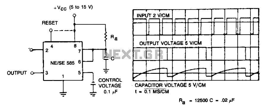
If the input frequency is known, the timer can be utilized as a frequency divider by adjusting the duration of the timing cycle. The figure illustrates the waveforms of the timer when employed as a divide-by-three circuit. This application...
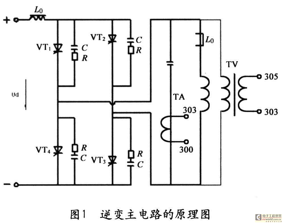
The starting ability of intermediate frequency power is a crucial performance index that significantly impacts the quality and usability of the apparatus. This has been a focal point and a challenge in the industry, leading to various methods aimed...
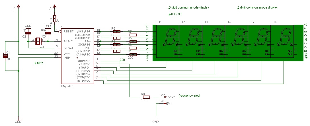
This frequency counter is designed to display the frequency from a frequency generator with an analog setting. It is a straightforward counter that can be utilized as a module within a box containing a frequency generator. The device measures...
Recently, I have needed to measure inductances in the hundreds of microhenries to several millihenry range. Though I have a pretty good LRC meter and an excellent bridge on my workbench in Mesa, Arizona, I wanted to make these...

This circuit generates sine and square wave signals with frequencies ranging from below 20 Hz to above 20 kHz. The advantage of this circuit diagram is that the output frequency can be adjusted by varying the variable resistor R6. The...
Warning: include(partials/cookie-banner.php): Failed to open stream: Permission denied in /var/www/html/nextgr/view-circuit.php on line 713
Warning: include(): Failed opening 'partials/cookie-banner.php' for inclusion (include_path='.:/usr/share/php') in /var/www/html/nextgr/view-circuit.php on line 713