
Stepper Motor Controllers

The described circuit serves as a basic stepper motor controller, leveraging standard electronic components to create an economical solution for driving stepper motors. The design typically includes a microcontroller or a simple control logic circuit that outputs control signals to the transistors, which act as switches to energize the motor coils in the correct sequence.
The circuit can incorporate a H-bridge configuration for bidirectional control of the stepper motor, allowing it to rotate in both clockwise and counterclockwise directions. Each transistor in the circuit is responsible for controlling one phase of the motor, enabling precise control over the stepping sequence.
To ensure compatibility with various stepper motors, the circuit should be designed to handle the motor's voltage and current ratings. The use of surplus transistors is advantageous as it reduces costs, but care must be taken to select transistors that can handle the necessary load without overheating.
Additionally, the circuit can be connected to a computer through a USB interface or a serial communication protocol, allowing for easy programming and control via software. This adaptability makes the circuit suitable for various applications, including robotics, CNC machines, and automated systems, where precise movement control is required.
In conclusion, this circuit represents a practical and economical solution for controlling stepper motors, making it accessible for hobbyists and professionals alike. Its simplicity and adaptability to computer control enhance its utility across a range of applications.The circuit is very simple and inexpensive. This is good thing because most commercial stepper motor controller ICs are quite expensive. This circuit is built from standard components and can easily be adapted to be controlled by a computer. If you use cheap surplus transistors and stepper motor, the price of the circuit can be kept to under $10.
🔗 External reference
Related Circuits
This circuit is 12 volt motors and lights well regulated. The scheme operates with PWM (Pulse Width Modulation). By IC1, a 555 is a square wave generated by a controllable duty cycle. This means that the width of the...
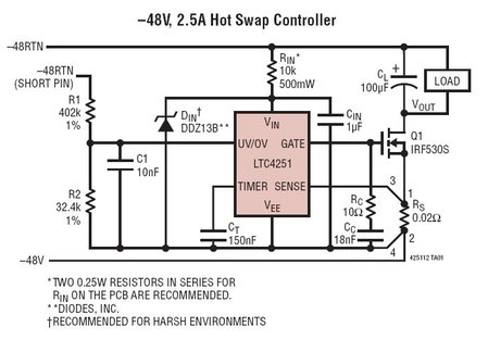
The LTC4251, LTC4251-1, and LTC4251-2 are negative voltage Hot Swap controllers designed to enable the safe insertion and removal of a board from a live backplane. The output current is managed through three stages of current limiting: a timed...
This circuit is beneficial for connecting a computer to homemade robotics. It is straightforward to construct and operate, capable of controlling two DC motors of varying current and voltage ratings, contingent on the specifications of the relays used. Additionally,...
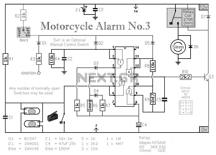
A CMOS-based motorcycle alarm circuit that features an intermittent siren output and automatic reset. It can be operated manually using a key switch or a hidden switch, and it can also be wired to set itself automatically. The CMOS-based motorcycle...

Controlling the speed of a three-phase AC motor is achieved by regulating the frequency of the power supply, as the motor operates in synchronization with the line frequency. A three-phase AC motor speed controller functions as a three-phase sine...
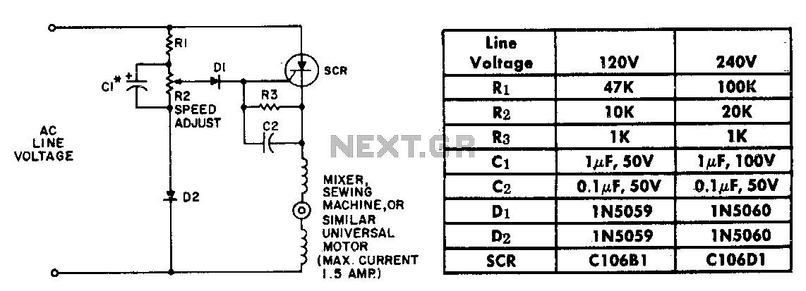
The resistor-capacitor network R1-R2-C1 generates a ramp-type reference voltage that is superimposed on an adjustable DC voltage controlled by the speed-setting potentiometer R2. This reference voltage, available at the wiper of R2, is compared against the residual counter electromotive...