
stepper motor controlling using uln2003

The ULN2003 is a versatile integrated circuit designed for driving high-current loads such as relays, motors, and lamps. It operates with a wide input voltage range and can handle significant output current, making it suitable for various applications in industrial and consumer electronics. Each of the seven channels can independently control a load, providing flexibility in circuit design.
The open collector configuration allows the ULN2003 to interface with different voltage levels, as the output can be connected to an external pull-up resistor. This feature enables the IC to be used in various configurations, including sinking current from the load to ground when activated by a logic input signal.
The typical input signal voltage range is compatible with TTL and CMOS logic levels, allowing easy integration into digital circuits. The internal structure of the Darlington pairs provides high voltage gain, ensuring that even low input signals can effectively drive larger loads.
Thermal management is an essential consideration when utilizing the ULN2003, particularly when operating at maximum current ratings. Adequate heat dissipation methods, such as heat sinks or thermal pads, should be implemented to maintain reliable operation and prevent thermal shutdown.
In summary, the ULN2003 is an efficient solution for driving high-power loads in a compact package, making it a preferred choice for engineers designing control circuits in various applications.The ULN2003 internally employs high voltage, high current darlington arrays each containing seven open collector darlington pairs with common emitters.Read More.. 🔗 External reference
Related Circuits
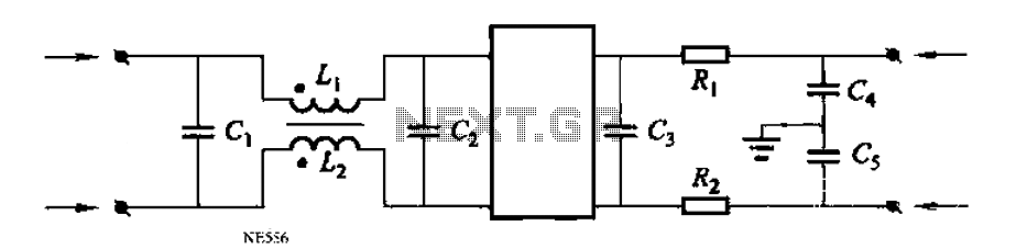
Automated instrumentation wiring using interference filters for the inverter is not as effective for harmonic processing. When operational, it will radiate a strong field strength due to high amplitude electromagnetic waves. If the meter is installed in the automation...
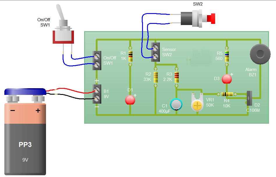
When the sensor switch SW2 is pressed, the LED D3 and the alarm are activated for a certain duration. The timing of the circuit is determined by the resistor R3 and capacitor C1. Additional details regarding the RC circuit...
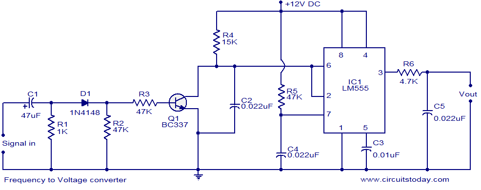
A simple frequency to voltage (F to V) converter circuit utilizing the LM555 Timer IC. This circuit has numerous applications in digital frequency meters, tachometers, and other related devices. The frequency to voltage (F to V) converter is a crucial...

This circuit diagram of a digital clock utilizes six common anode seven-segment displays to indicate the time. It does not require microcontrollers or PICs for operation. The circuit operates using the MM5314 integrated circuit, functioning at either 50 Hz...
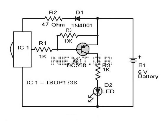
A simple remote control tester circuit with a diagram and schematic using the infrared sensor IC TSOP1738. An LED will blink when infrared waves fall on it, indicating the remote control is functioning. The remote control tester circuit utilizes the...
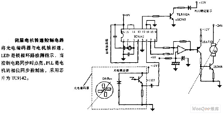
The servo motor speed control circuit connects the photoelectric encoder to the motor shaft. The LED serves as an indicator light for the phase-locked loop (PLL) detection, illuminating when the control circuit is synchronized. The PLL employs a phase...