
Stepper

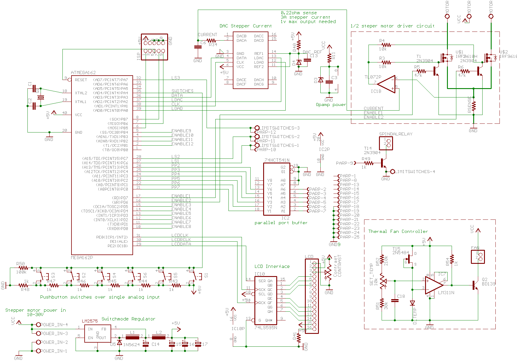
The circuit design incorporates a stepper motor driver that utilizes a microstepping approach to enhance motion smoothness and precision. The driver operates by controlling the current through the motor windings, allowing for finer control over the stepper motor's position. The D-A converter plays a crucial role in translating digital signals into analog currents, enabling the driver to energize specific windings based on the desired step position.
In terms of layout, careful consideration is given to the placement of components to minimize interference and optimize performance. The PCB design should facilitate efficient heat dissipation and accommodate the required voltage levels for both the stepper motor and control circuitry. The use of decoupling capacitors near the power supply pins of the ICs ensures stability during operation, reducing noise that could affect the performance of the stepper motor.
The timing diagram included in the documentation illustrates the sequence of control signals sent to the stepper motor, highlighting the timing relationships between different phases of operation. This is critical for ensuring that the motor operates smoothly and accurately follows the intended trajectory during celestial tracking.
Future enhancements may involve integrating feedback mechanisms for improved accuracy, such as optical encoders that provide real-time position data to the control system. This would allow for closed-loop control, further enhancing the system's performance and reliability in astronomical applications.The resistors R18 and R22 that should have been connected to pin 8 of U4 were mistakenly connected to pin 9. The present versions have been corrected. A minor error on the component layout is that there are two versions of C2, in the upper right and lower left corners - let one of them read C11 instead (they are equal).
This is not corrected on the image. Here is the latest schematic by David H Bevel - I have updated the text with his parts numbering (I hope, but I may have missed occasionally!). This schematic, the parts list and the PCB pattern (Full scale at 500 dpi - or a 1:4 version for viewing ) (note that the pattern is seen from the component, NOT the copper side!) and an alternate PCB pattern with less copper etched away, as well as the component layout and the timing diagram are mutually consistent - I am sure. Also, here is a diagram of the connections and a picture of Dave`s version built and ready - Thanks a lot Dave for all the work you`ve done !
Folks, please respect our copyrights. Next in the pipeline - the modification necessary to use a low-voltage stepper motor using 3V supply (and 12v for the control circuit). If this is of interest to you, mail me at nilsolof. carlin@telia. com. This circuit was designed primarily to feed a 5. 25" floppy-disk type stepper, driving a threaded rod, but may be used with other platform designs. It features: I`ve been using an equatorial platform for my 13. 1" and 6" Dobs. I consider the platform a very useful addition - a full GoTo mount can do more, but I think the mechanical complexity is also in another league.
It is of course particularly useful for planet studies - not least if you like to show planets to friends and acquaintances, as you do not need to re-position the telescope every minute! However, the full-step circuit I have been using (until I made the circuit described here) introduces enough vibration to wipe out much of the detail (particularly with my 6"), and I`ve been wishing for a better driver.
Running the stepper faster using more gearing down might have helped, but I wanted a fast rewind with my threaded rod driver, and some 3 minutes of rewind after an hour of use was already near the limit of acceptability. Recently I started to build an interface circuit for Mel Bartels` Scope Drive, to use with my old SP-C6 as a pilot project before trying with my Dobs (the stepper motors and mechanics are already there, and no position feedback is needed - but the gearing seems to preclude fast slewing.
). Experimenting with this has already produced interesting spin-off in the form of a computer controlled tester stage for Foucault and related tests described elsewhere. After experimenting with pulse-width modulation, it was quite clear to me that I should try a different approach (with all respect to Mel, though I admit that the pulse-width modulation he uses does work, but it is very noisy!).
I attached a 3-bit (plus sign bit to decide which half of the winding to energize) D-A converter, using analog microstepping. Not quite unexpectedly, I found the motion of this very much smoother. So on to designing a circuit - it was a long while ago since I did much electronic design, but I had a lot of components left.
, meaning it should turn 1. 75 turns/min or 0. 029 turns/sec - with a 200 step motor (and no gears) this means 5. 8 full steps/second. This means the stars near the celestial equator will move 15/5. 8 ~ 2. 6 arcsec/fullstep, far more than the resolution of the telescope at 0. 7 arcsec of Dawes` limit for my 6". With my old driver I used a primitive gear of appr 6:1, giving a celestial motion of 0. 4 arcsec between steps - clearly, resonances in my 6" amplified this. Vib 🔗 External reference
Related Circuits
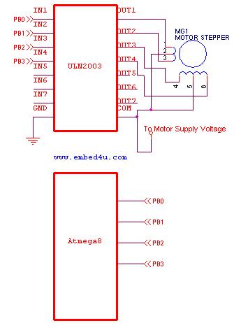
This tutorial utilizes the ATmega8 microcontroller with a 4 MHz crystal oscillator and unipolar stepper motors. The ULN2003, a Darlington pair driver integrated circuit, is employed for motor control. The ATmega8 microcontroller is a versatile 8-bit device from the AVR...
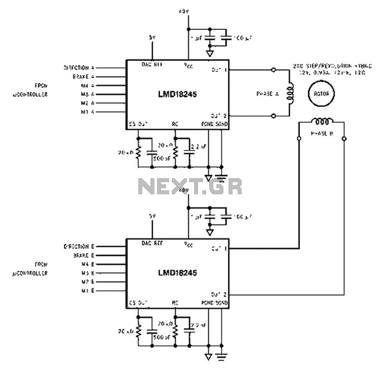
An innovative current detection method eliminates the power loss associated with the sense resistor in series with the motor. A 4-digit analog converter (DAC) facilitates digital control of the motor current path, simplifying the implementation of full, half, and...
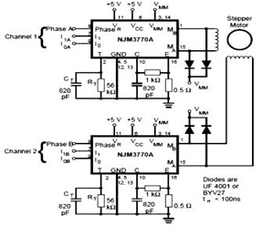
The schematic below represents a typical stepper motor driver application utilizing the NJM3770A. As illustrated in the diagram, the single-channel stepper motor drivers NJM3717 and NJM3770A operate independently and are not synchronized. The circuit design features the NJM3770A, a dedicated...
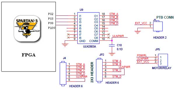
The Spartan-3 Primer board features external stepper motor interfacing, as illustrated in the accompanying figure. The stepper motor is driven by a ULN2803A, which is a high-voltage, high-current Darlington transistor array. The ULN2803 is utilized as a driver for...
The project involves using a 6-wire linear actuator to slowly push a syringe pump. The motor utilized is a custom Hurst SLS model acquired from a surplus dealer in Silicon Valley, rated at 12VDC and 11.5W, which translates to...
A basic CNC machine was built for a university project, and the completed machine will undergo upgrades over the coming months. The plan includes replacing the small 48-step stepper motors with larger 200-step motors to enhance performance. The project involves...