
Stereo Noise Reduction Circuit

The noise reduction circuit operates on the principle of detecting silence or low audio signals, which are typically the moments when unwanted noise becomes noticeable. The circuit employs a combination of analog and digital components to achieve effective noise suppression.
At its core, the circuit includes a signal detection module that monitors the audio input for periods of low amplitude. When the input signal falls below a predetermined threshold, the circuit activates a variable gain amplifier (VGA) or a digital signal processor (DSP) that reduces the output signal level. This attenuation can be adjusted based on the severity of the noise detected, allowing for a customizable response to different audio environments.
In addition to the VGA or DSP, the circuit may incorporate a low-pass filter to further refine the audio signal by removing high-frequency noise components that can be particularly intrusive during silent periods. The filter's cutoff frequency can be tailored to suit the specific application, ensuring that the desired audio quality is maintained even while noise reduction is active.
Feedback mechanisms can also be integrated into the design to monitor the effectiveness of the noise reduction process. This feedback loop can help optimize the attenuation levels dynamically, ensuring that the circuit responds appropriately to varying audio conditions.
Power supply considerations are crucial for the circuit's performance. A regulated power supply is recommended to ensure consistent operation, particularly in environments with fluctuating voltage levels. Furthermore, careful selection of components, such as low-noise operational amplifiers, can significantly enhance the overall performance of the noise reduction circuit.
Overall, this noise reduction circuit is a valuable addition to audio systems, providing a smoother listening experience by effectively managing unwanted noise during quiet moments in music playback.The noise reduction circuit is based on the observation that noise is always disturbing in intervals when music stops. It will attenuate the signal output.. 🔗 External reference
Related Circuits

The SLB0586A integrated circuit from Siemens can be utilized to construct a straightforward touch light dimmer circuit, enabling the user to modify the intensity of a lamp. This circuit also incorporates a TIC206D component. The SLB0586A is a specialized touch-sensitive...
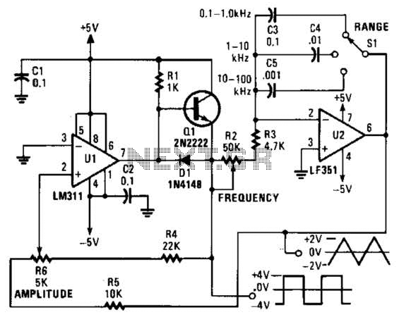
This is a simple triangle-wave generator utilizing two integrated circuit (IC) devices and a transistor. The triangle wave serves as feedback to the square-wave generator. It allows range switching across three intervals from 100 Hz to 100 kHz. Additional...

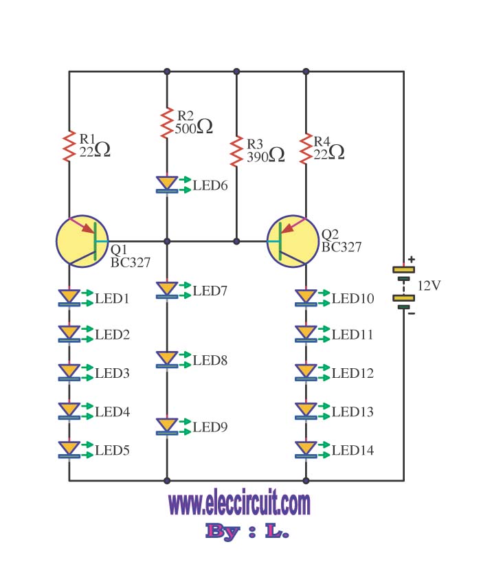
This is a concise guide for constructing a stereo VU meter utilizing the LM3915/LM3916 integrated circuits. The LM3916 is designed to convert analog voltage levels into visual representations through the activation of 10 LEDs, LCDs, or vacuum fluorescent displays,...
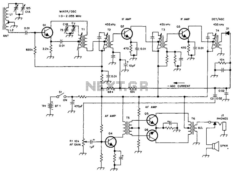
A schematic of a typical transistor AM radio is presented. This circuit utilizes npn transistors. It is a generic circuit; hence, specific values for some components are not provided. This circuit serves as a reference point for experimenters. The schematic...

This is a false capture circuit or lie detector circuit. The basic principle is based on the resistance of human skin. While dry skin has a resistance of about 1 Megaohm. The lie detector circuit utilizes the principle of galvanic...
This circuit enables the brake light to flash. The default behavior occurs when power is supplied to the circuit or when the brake is engaged. The timer IC (IC2) drives current to the transistor (Q2), producing an oscillating output...