
StunGun circuit

The Electronic Dazer operates using a high-voltage generation circuit designed to produce a significant electrical discharge. The core component is typically a DC to DC converter, which steps up a low voltage input from a battery (often a 9V or 12V battery) to a high voltage output. The circuit may utilize components such as a transformer, oscillators, and capacitors to achieve the desired voltage levels.
The design might include a square wave oscillator to drive the transformer, allowing for efficient energy transfer during the voltage step-up process. This oscillator can be implemented using a simple transistor or a dedicated IC, which generates a high-frequency signal. The transformer steps up the voltage to the desired level, in this case, around 2,000 volts, which is sufficient for personal protection applications.
To enhance the voltage output, additional multiplier stages can be integrated into the circuit. These stages typically consist of diodes and capacitors arranged in a Cockcroft-Walton configuration, which allows for further voltage multiplication without significantly increasing the size of the transformer. However, it is essential to consider that adding more stages will increase the physical dimensions of the device and may also introduce complexities in circuit design and stability.
Safety precautions must be emphasized when working with high-voltage circuits. Proper insulation, secure casing, and warning labels are critical to prevent accidental contact with high-voltage terminals. Additionally, the device should only be used in controlled environments, considering the potential for harm if misused.
Overall, the Electronic Dazer serves as a practical example of high-voltage circuit design, highlighting the balance between portability, functionality, and safety in personal protection devices.The Electronic Dazer is a modern, portable, personal-protection appliance. It generates hight potential energy to ward off vicious animals or other attackers. It is an aid to help exape from a potentially dangerous situation. the device develops about 2,000 volts. Higher voltages mabe be attained by adding aditional multiplier stages, but it should be noted that those stage will also increase the overal size of the unit. WARNING: THIS DEVICE IS NOT A TOY! We present it for EDUCATIONAL and EXPERIMENTAL purposes ONLY. The circuit develops about 2000 volts at a respectable amperage. It can cause you pain and even damage if you become careless and touch its output terminals. 🔗 External reference
Related Circuits
The latest addition to the collection of Infrared (IR) Repeater circuits, the Mark 5, is an enhanced version of the Mark 1 circuit and features an increased range. The Mark 5 Infrared Repeater circuit is designed to extend the range...
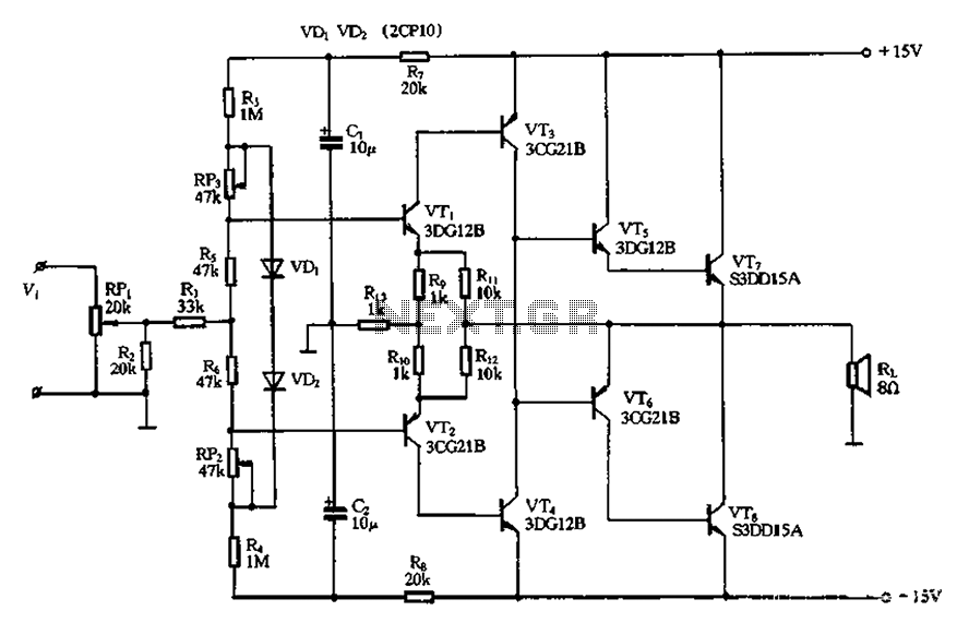
The circuit utilizes diode VDi, f Pooh to stabilize the base bias of transistors VTi and VT2, ensuring a more stable quiescent point when the supply voltage is within a specific range. In the event of temperature fluctuations, the...
Running Message Display Circuit Diagram. This circuit is based on the CD401 IC. Features: Light emitting diodes are advantageous due to their smaller size. The Running Message Display Circuit utilizes the CD401 integrated circuit, which is a versatile component in...
XP power plug, FU fuse, ST temperature control, T1 low-voltage transformers, S1, S2 door interlock switch, S3 threshold control switch, RT thermal sensor, K1, K2 relay, EL furnace light, M1 wheel motor, M2 fan motor, T2 high-voltage transformer, C...
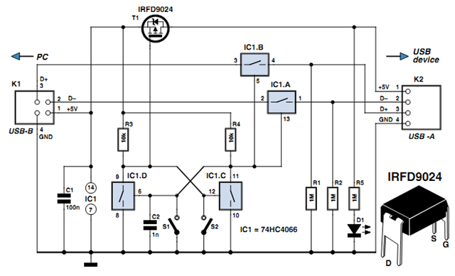
Individuals engaged in the experimentation or development of USB-connected peripheral hardware often find it frustrating to repeatedly disconnect and reconnect the plug to reestablish communication with the PC. This procedure is necessary, for instance, every time the peripheral device...

This is a simple headphone amplifier circuit designed to drive headphones when a music player lacks sufficient power. The circuit is straightforward and utilizes only three transistors. The first transistor, Q1 (BC 239), along with its associated components, functions...