
Switch Debouncing

The described circuit employs a 555 timer in a monostable configuration to effectively debounce a normally open push button switch (PBS). The primary function of this circuit is to eliminate unwanted transient spikes and contact bounce that may occur when the switch is pressed or released. In this setup, the 555 timer generates a single output pulse of approximately 20 milliseconds whenever the push button is activated.
The circuit's design includes a timing component that ensures the output pulse duration can be adjusted by changing the resistor and capacitor values connected to the 555 timer. The output pulse duration is crucial for ensuring that any mechanical bouncing of the switch contacts does not result in multiple unwanted pulses being registered in the connected circuitry.
To further enhance the reliability of the debouncing mechanism, a secondary timing circuit is integrated, consisting of a 1 Megohm resistor and a 47 nanofarad capacitor. This additional timing circuit serves to prevent the 555 timer from being retriggered while the input remains low longer than the output pulse. When the push button is pressed, the capacitor charges through the resistor, and this RC time constant helps to ensure that the timer output remains stable and is not inadvertently retriggered by continued contact bounce.
In summary, this circuit configuration provides a robust solution for debouncing a push button switch, making it highly suitable for applications where precise switch activation is critical. The use of the 555 timer in monostable mode, combined with the additional timing elements, ensures that the output remains clean and free from noise, thereby improving the overall performance and reliability of the electronic system in which it is implemented.This circuit will remove the transient spikes and contact bounces from a non-latching push button switch. Using a 555 timer as a monostable circuit, it is easy to build a good switch debouncer circuit. There are many circuits for SPDT debouncing, but not many for a normally open, push-to-make press button switch (PBS).
The 555 monostable gives an output pulse of around 20 msec with component values shown. The 555 circuit can be re-triggered if the input is held low longer than the output pulse. To prevent this happening, I have included a further timing circuit comprised of the 1Meg resistor and 47n capacitor. Normally, the 47n capacitor is discharged via 🔗 External reference
Related Circuits
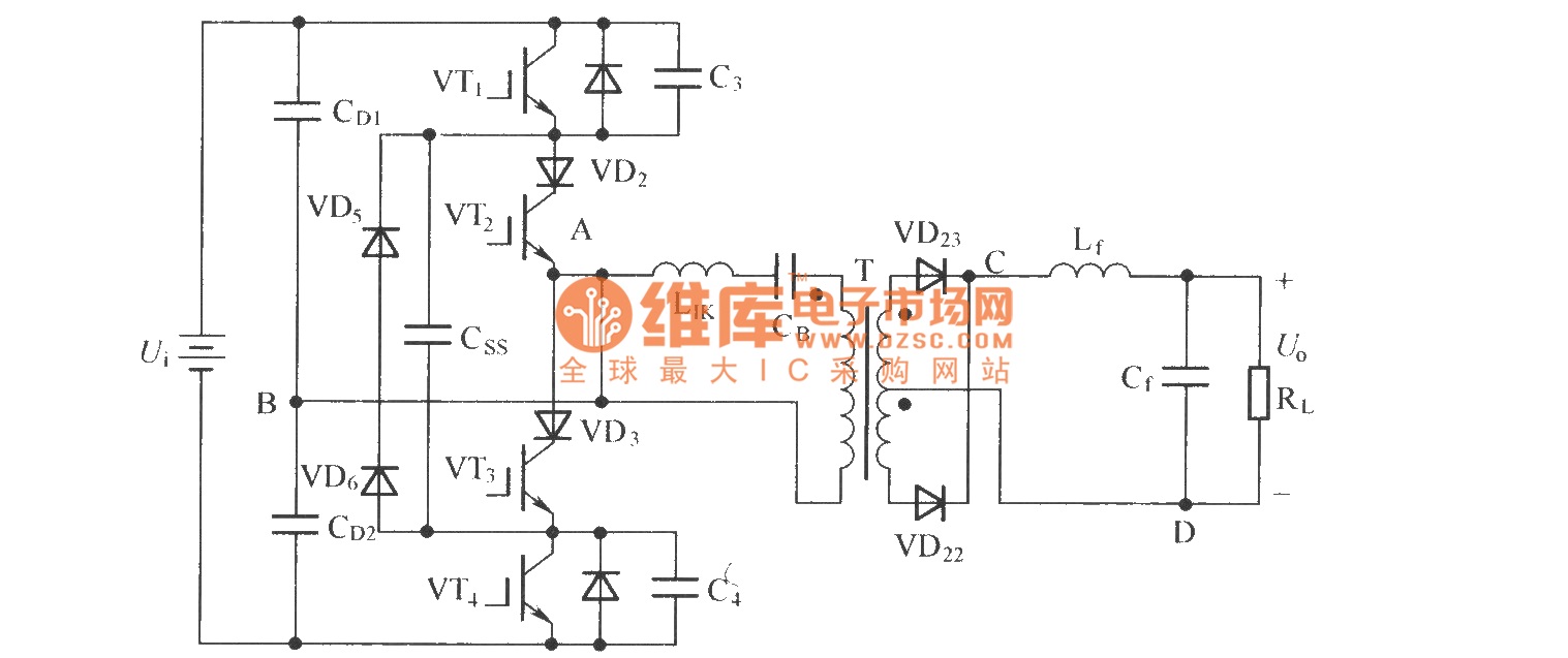
To eliminate circulating current in a zero-voltage switch three-level DC converter during its zero state, a zero-voltage zero-current switch three-level DC converter circuit has been proposed. The primary distinction between this circuit and the standard zero-voltage switch three-level DC...

This circuit serves as an alarm system suitable for both home security and personal belongings such as handbags. When installed in a home, it can be positioned on doors or windows, and when used for bags, it provides a...
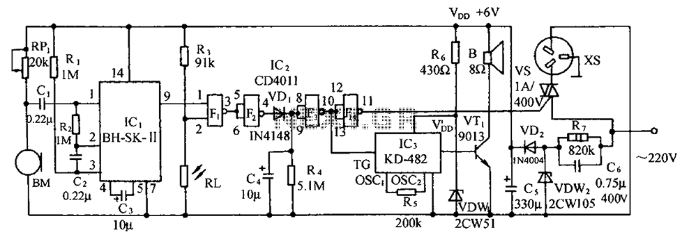
The circuit illustrated includes a sound transducer sensing switch, an electrical light control switch, an SCR control circuit, a vocal music circuit, and an AC step-down rectifier circuit. The circuit comprises several interconnected components that serve distinct functions, allowing for...
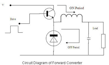
Switched Mode Power Supplies (SMPS) are categorized as DC to DC converters and DC to AC converters. Switched Mode Power Supplies (SMPS) are essential components in modern electronic devices, providing efficient power conversion from one form to another. The primary...
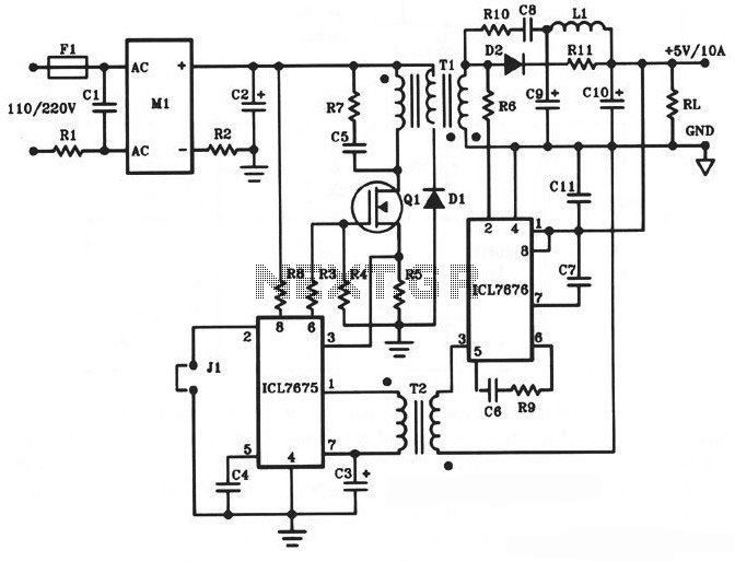
The following diagram illustrates a 50W offline switching power supply circuit design. This circuit is powered by a MOSFET, specifically the BUZ80A/IXTP4N8 for a 220V AC voltage input and the GE IRF823 for a 110V AC voltage input. The...
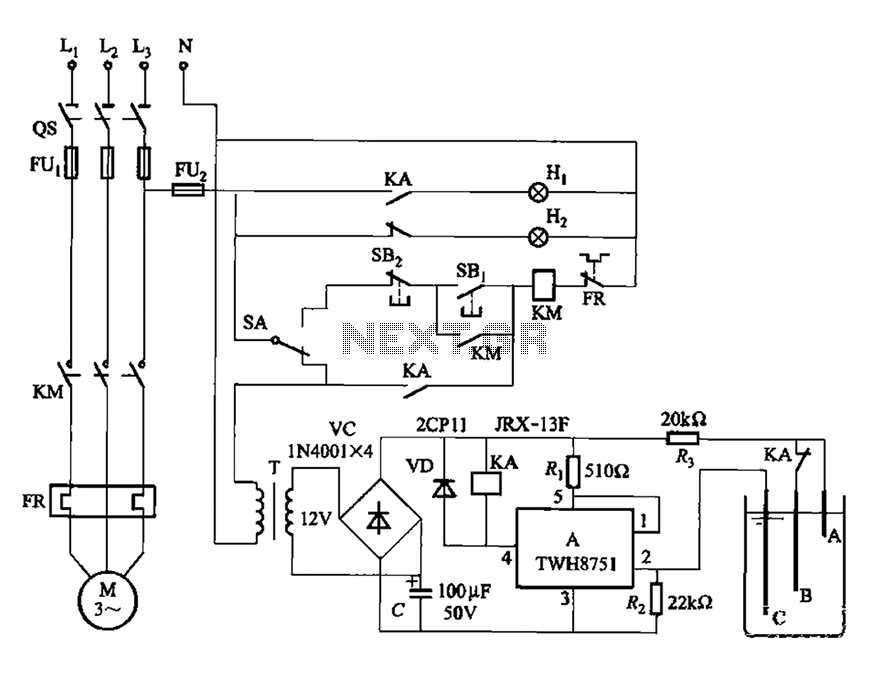
The power switch integrated circuit A features a straightforward design with high sensitivity, ensuring reliable operation. It is part of an automatic liquid level control circuit. When the water level at electrode B drops below 2 feet (0V), circuit...