
SWR warning indicator

The circuit involves an operational amplifier configured in a feedback loop to process the DC voltage signal derived from the SWR meter. The SWR meter measures the ratio of the power reflected from the load to the power delivered to the load, providing an indication of the efficiency of the antenna system. The output voltage from the SWR meter is fed into the non-inverting input of the op amp.
To enable adjustment of the SWR reading, a potentiometer is included in the circuit. This potentiometer allows for fine-tuning of the reference voltage applied to the inverting input of the op amp. As the potentiometer is adjusted, the threshold at which the op amp will activate the LED changes, indicating a specific SWR level.
The op amp is configured in a comparator mode, where it compares the voltage from the SWR meter against the adjustable reference voltage. When the voltage from the SWR meter exceeds the set threshold, the output of the op amp goes high, turning on the LED. This visual indication serves as an alert to the user that the SWR has reached a predetermined level, necessitating attention to the antenna system.
Power supply considerations for the op amp must also be addressed, ensuring that it operates within its specified voltage range. Proper decoupling capacitors should be placed close to the op amp’s power pins to mitigate any noise that could affect performance. Additionally, the selection of the op amp should consider bandwidth and slew rate to accommodate the frequency response of the SWR meter.
Overall, this circuit design provides a straightforward method for monitoring SWR levels, enhancing the usability of the antenna system by providing a clear visual indication when the SWR exceeds acceptable limits.Op amp with dc input from SWR meter can be adjusted to preset the SWR reading at which the LED lights.
Related Circuits
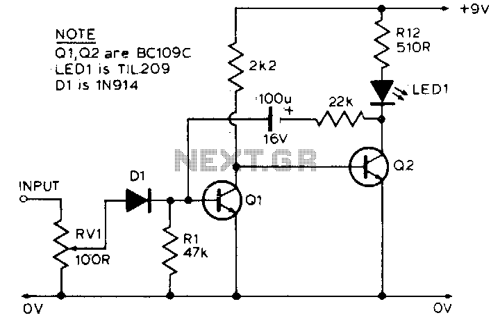
The LED is normally lit, but it will be briefly extinguished if the input exceeds a preset level (set by RV1). A possible application is to monitor the output voltage across a loudspeaker; the LED will flicker with large...
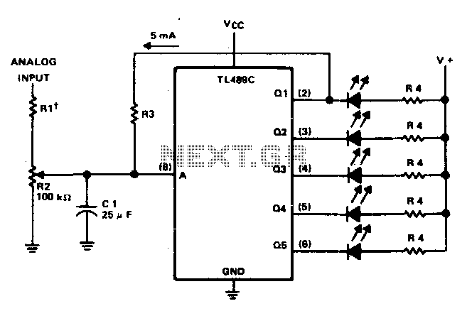
This circuit offers a visual representation of the input analog voltage level. It features a high input impedance at pin 8 and open-collector outputs that can sink up to 40 milliamperes. It is designed to drive a linear array...
This circuit indicates audio output power using three LEDs. It serves as a useful addition to an amplifier. The audio output power indicator circuit is designed to visually represent the power level of an audio amplifier through the use of...
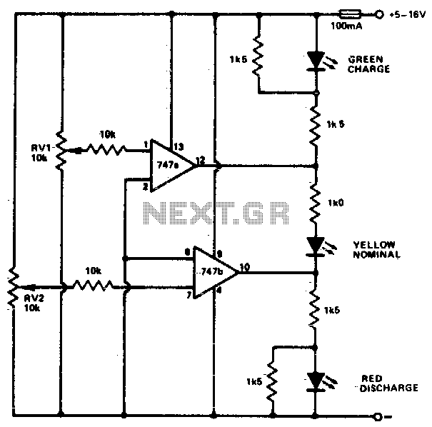
This circuit monitors car battery voltage and indicates nominal supply voltage, as well as low or high voltage conditions. RV1 and RV2 are used to adjust the thresholds at which the red/yellow and yellow/green LEDs activate or deactivate. For...
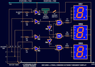
Circuits designed to indicate water levels typically consist of LEDs to represent the liquid level. However, this circuit utilizes a 7-segment LED display instead of standard LEDs for a numeric representation of the water level. Additionally, a buzzer is...
The Inter-Power SWR-5 upper right isn't worth a penny. Got it from a mate to use with a beacon, but I burnt it out with only 3.5-4W morse signal on 70cm. Removed the bridge and installed my own pick-up...