
TDA3910 Internal Block Diagram

The TDA3810 is an integrated circuit designed for audio processing, specifically targeting applications that require versatile audio signal manipulation. The internal block diagram highlights the architecture that enables the device to switch between different modes of operation seamlessly, allowing for enhanced audio experiences.
In mono channel mode, the TDA3810 accepts a single audio input and processes it to produce a high-quality analog output. This mode is particularly useful in applications where stereo signals are not available, ensuring that audio playback remains clear and intelligible.
When operating in stereo mode, the circuit can handle two separate audio channels, allowing for a richer sound experience. This mode is ideal for applications that utilize standard stereo audio sources, enabling the TDA3810 to deliver precise audio reproduction with distinct left and right channel separation.
The stereo widening mode, or surround sound mode, is where the TDA3810 showcases its advanced capabilities. In this mode, the circuit employs various algorithms to enhance the spatial characteristics of the audio signal, creating an immersive listening experience that simulates surround sound environments. This is particularly advantageous in home theater systems and audio playback setups where users seek to replicate the acoustics of live performances or cinematic experiences.
Overall, the TDA3810's design and operational versatility make it a valuable component in modern audio applications, catering to a wide range of user needs while maintaining high fidelity and performance standards.Figure 1-123 is an internal block diagram of the TDA3810 o The circuit can operate in three modes of operation: (1) may be mono channel stereo signal into an analog signal; (2) can work in stereo status; (3) can work in stereo widening state or state called surround sound.
Related Circuits
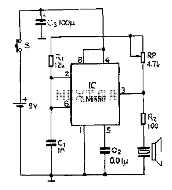
A 40 kHz ultrasonic transmitter circuit utilizes the LM555 timer as a time base circuit along with external components to create a 40 kHz multivibrator. The resistance of the adjustable resistor RP can modify the oscillation frequency. The output...
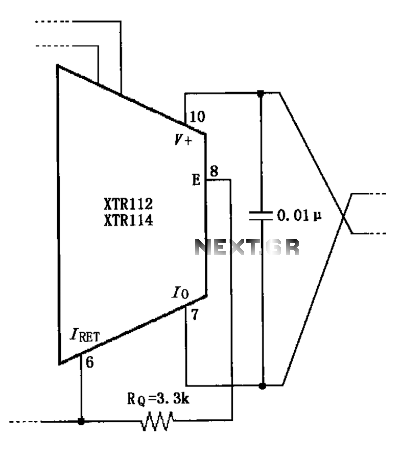
When not using the external transistor Q1, a 3.3k resistor should be connected between the pins and legs. This connection causes internal power dissipation, which will affect accuracy and lead to a decline in performance. The circuit in question involves...
%2Bwith%2Banimation%2Bsimulation%2Bcircuit.png)
The Johnson digital counter, also known as the Twisted Ring Counter, is a synchronous shift register that incorporates feedback from the inverted output (Q`) of the last flip-flop. The Q` output of the final flip-flop is connected back to...
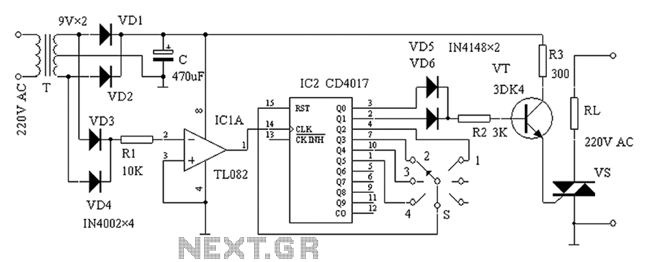
The zero-power regulator circuit is simple, reliable, and functional. It is suitable for various electric power adjustment applications, such as series-wound motor power adjustment. The operational principle of the circuit involves several components, including the power circuit, an AC...
The following circuit illustrates an Ultrasonic Receiver Circuit Diagram. This circuit is based on the CA3140 integrated circuit. Features include the frequency of sound produced. The ultrasonic receiver circuit utilizes the CA3140 operational amplifier, known for its high input impedance...

The thermistor RT, along with resistors R1, R2, R3, and variable resistor RP1, creates a temperature measurement bridge. At a temperature of 20°C, the configuration of R1, R3, and the adjustment of RP1 enables the bridge to maintain balance....