
Telephone Free Indicator

The described circuit utilizes a diac, a type of semiconductor device that exhibits a sharp change in conductivity at a specific voltage threshold. In this application, the diac is employed to control the illumination of an LED based on the voltage present on the telephone line. The circuit is designed to operate within the specified voltage range and to respond appropriately to variations in line voltage.
The resistor R1 plays a critical role in limiting the current flowing through the diac and the LED. When the line voltage exceeds the diac's breakdown voltage, it conducts, allowing current to flow and illuminating the LED. The choice of R1's resistance value is crucial, particularly when considering the maximum line voltage. If the line voltage is consistently above 50 volts, increasing R1's value will help to prevent excessive current that could damage the components.
The inclusion of a bridge rectifier is a significant enhancement to the circuit's versatility. By allowing for both polarities of the incoming voltage, the circuit can function correctly regardless of the orientation of the telephone line connection. This is particularly useful in regions where telephone line polarity may vary based on the service provider or local regulations.
In summary, this circuit effectively demonstrates the use of a diac and LED to create a visual indicator based on telephone line voltage. The addition of a bridge rectifier ensures compatibility with varying line polarities, while careful selection of resistor values helps maintain safe operating conditions for the components involved. However, it is imperative to adhere to local regulations and standards, as this particular design is not approved for connection to the PSTN in the UK.Depending on local regulations and the telephone company you happen to be connected to, the voltage on a free telephone line can be anything between 42 and 60 volts. As it happens, that`s sufficient to make a diac conduct and act like a kind of zener diode maintaining a voltage of 38 V or so.
The current required for this action causes the green h igh-efficiency LED in the circuit to light. Line voltages higher than about 50 V may require R1 to be changed from 10 k to a slightly higher value. When the receiver is lifted, the line voltage drops to less than 15 V (typically 12 V) causing the diac to block and the LED to go out.
The circuit diagram indicates + and with the phone lines. However, in a number of countries the line polarity is reversed when a call is established. To make sure the circuit can still function under these circumstances, a bridge rectier may be added as indicated by the dashed outlines. The bridge will make the circuit independent of any polarity changes on the phone line and may consist of four discrete diodes, say, 1N4002`s or similar.
Finally, note that this circuit is not BABT approved for connection to the public switched telephone network (PSTN) in the UK. 🔗 External reference
Related Circuits
Voltage fluctuations in the mains are a common phenomenon. These fluctuations can cause significant damage to expensive electronics and electrical devices that operate for extended periods. To address this issue, an automatic stabilizer is typically employed, which can be...
This circuit is designed for speech activity detection in telephone lines. It is particularly useful for half-duplex conversations between two stations, where simultaneous transmission of voice and data occurs over the same pair of cables by interspersing data with...
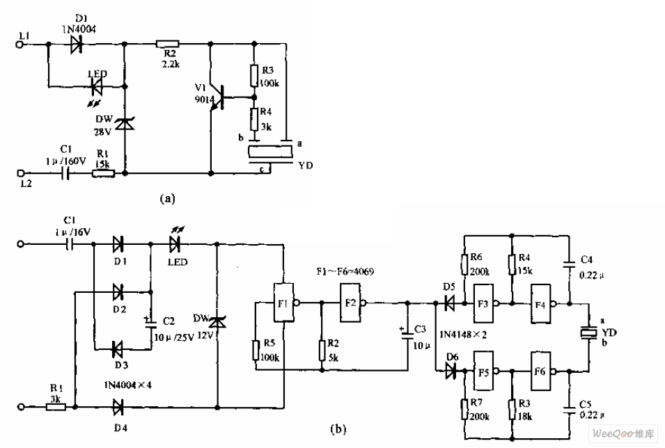
The telephone electronic ringer circuit is illustrated in the provided figure. It features an NPN transistor (either 9014 or 3DG12) as the primary component. The sound device, referred to as YD, functions as both a feedback device and is...
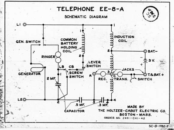
One unit is housed in a leather bag and is identified as model EE-8-A. One or more units are contained in a canvas bag and are designated as EE-8-B. All models feature handsets equipped with a butterfly push-to-talk lever....

When the lamp turns off, a reset pulse is generated for the corresponding counter by NAND gate IC1. The counter then counts up again. The display's progression rate can be adjusted to the desired speed using potentiometer P1. Only...

While owning a modern NiCd battery charger is advantageous, there may still be instances where an incompatible battery is encountered, such as one with an unusual voltage requirement or a need for a higher charging current than what a...