
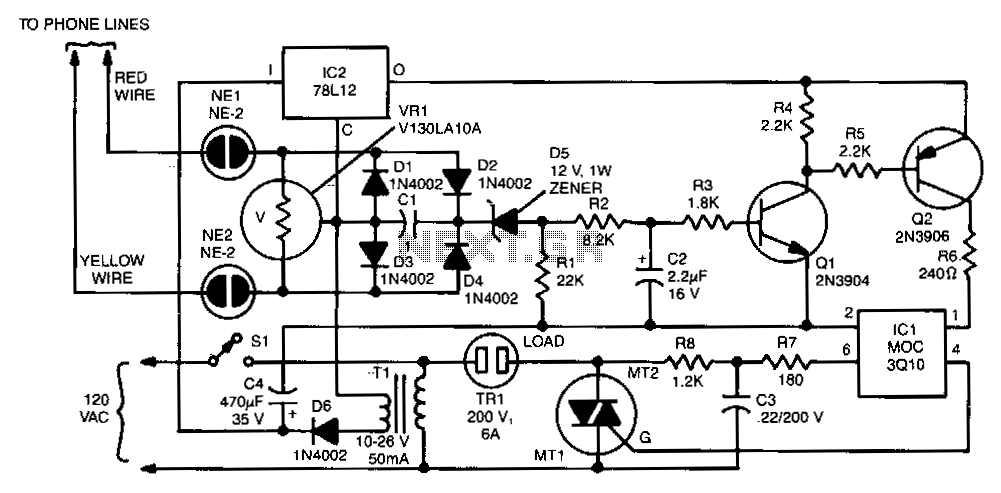
Telephone hold button

The circuit described involves a telephone line hold mechanism utilizing a silicon control rectifier (SCR) and several passive components. The system operates under two primary states: on-hook and off-hook. In the on-hook state, the voltage across the red-green wires remains at approximately 48 volts DC, indicating that no telephone is actively using the line. When a telephone goes off-hook, it draws current, which reduces the voltage to below 5 volts DC, indicating active use of the line.
The SCR, designated as SCR1, plays a crucial role in maintaining the hold state of the call. When a user hangs up the phone while keeping switch S1 depressed, the voltage across SCR1's gate becomes sufficient to trigger conduction, allowing current to flow through the circuit. This current path includes diode D1, LED1, and resistor R1, with R1 providing a load of 1500 ohms. This resistance is carefully selected to ensure that the line can be seized without exceeding the safe operating current for LED1, which visually indicates that the line is held.
Once the telephone is placed off-hook again, the voltage across the red-green wires drops substantially. The voltage drop across D1 (0.7 volts) and LED1 (2.0 volts) leaves insufficient voltage for SCR1 to remain conductive, as only 2.3 volts is available. Consequently, SCR1 turns off, effectively releasing the hold on the line. This design ensures that the system can seamlessly transition between holding a call and releasing it based on the state of the telephone, thereby maintaining proper line management and user control.The on-hook (no load) voltage across the red-green wires will be 48 V or slightly less when all telephones are on-hook (disconnected). When any telephone goes off-hook the load current flowing in the telephone causes the voltage to fall below 5 volts dc.
Although the telephone hold is connected across the red-green wires, silicon control rectifier SCRl is open; so there is no current path across the telephone line. To hold the call, depress normally-open switch SI and hang up the telephone (still depressing SI). When the phone goes on-hook the red-green voltage jumps to 48 volts dc. Since switch SI is closed, a positive voltage is applied to SCRl's gate, which causes SCRl to conduct, thereby completing the circuit across the telephone line through Dl, LED1, Rl, and SCRl.
The current that flows through those components also causes the LED to light up—indicating that the telephone line is being held. The effective load across the red-green wires is the 1500 ohm value of Rl, which is sufficient to seize the line while limiting the current through the LED to a safe value.
When the telephone, or an extension, is once again placed off-hook the red-green voltage falls to 5 volts or less. But diode Dl has a normal voltage drop—called the breakover voltage—of 0.7 volts, and the LED has a forward drop of 2.0 volts.
Excluding the voltage drop across Rl there is a maximum of 2.3 volts available for SCRl, which is too low to maintain conduction; so SCRl automatically opens the hold circuit when any telephone goes off-hook.
Related Circuits
The two neon bulbs will illuminate when the voltage across the ringing circuit exceeds 100 V. These bulbs provide line isolation between the unit and the telephone line. Additionally, they function as a voltage divider for the bridge rectifier...
Telephones are declining globally; however, India has over 350 million mobile phone users, alongside a significant number of traditional telephone users. This telephone timer is designed to save costs by controlling unnecessary time spent during phone calls. This simple...
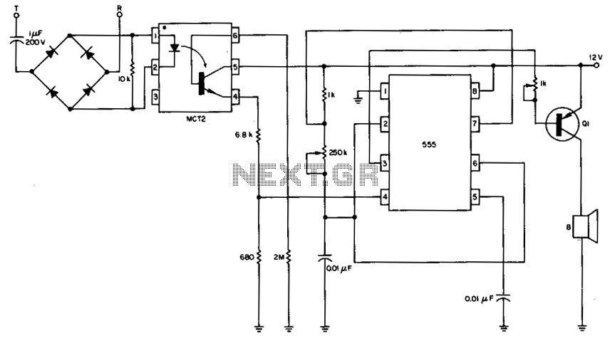
The 555 timer is configured as a multivibrator in conjunction with an opto-isolator to drive a remote speaker. The circuit utilizes the 555 timer in astable mode to generate a continuous square wave output. This output is then used to...
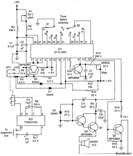
The core component of the circuit is IC1, the AY-3-1350 melody synthesizer IC from General Instrument. IC2 is a TCM1512 telephone ring detector IC powered by the telephone line. The circuit operates when IC2 detects a ring pulse on...
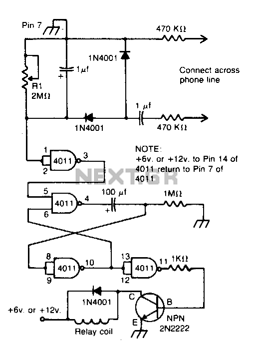
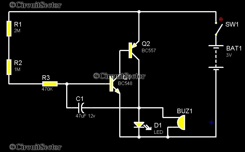
Connected across the bell circuit of a phone, this circuit activates a relay when the phone is ringing. It can utilize delay contacts to operate any bell, siren, buzzer, or lamp. The described circuit functions as a relay activation mechanism...
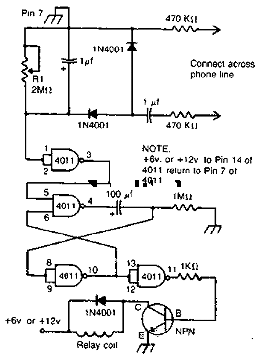
By cross-connecting the telephone ringing circuit, when the phone rings, the circuit activates the relay. It utilizes a delay in contact to drive various devices such as bells, sirens, buzzers, or lights. The telephone ringing circuit is designed to detect...