
Temperature Alarm with Op-Amp Comparator
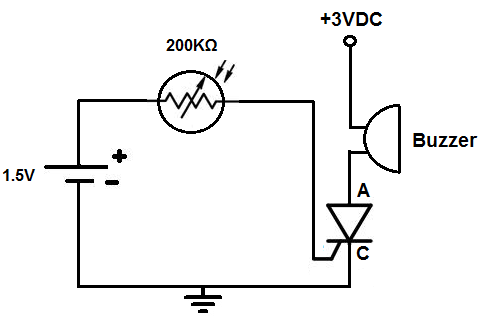
The comparator circuit functions by comparing two input voltages and producing a digital output that indicates which input is higher. In this configuration, the non-inverting input receives a fixed reference voltage determined by the resistor divider formed by R1 and R2. This reference voltage is crucial for setting the threshold at which the comparator toggles its output state.
The inverting input voltage is typically derived from a variable source, allowing the circuit to respond to changes in this input. The output of the comparator will switch states when the voltage at the inverting input exceeds the reference voltage at the non-inverting input. This characteristic makes the comparator useful in various applications, such as zero-crossing detectors, level shifters, and signal conditioning circuits.
To ensure stable operation, it is important to select appropriate resistor values for R1 and R2, considering the desired reference voltage and the input voltage range. Additionally, the circuit may benefit from hysteresis to prevent rapid switching in the presence of noise, which can be implemented by adding positive feedback through a resistor connected from the output back to the non-inverting input.
Overall, the comparator circuit is a fundamental building block in electronic design, enabling precise voltage comparisons and control in a wide array of applications.The circuit below is configured as a comparator. A fixed reference voltage at the non inverting input is provided by R1 and R2. The inverting input voltage is.. 🔗 External reference
Related Circuits

A filtered 15 V DC supply is applied to a series circuit that includes a thermistor (R2) and a parallel combination of resistors (R1 and R3). The transistor (Q1) functions as a switch, with its state controlled by the...

This is a complete alarm system with 5 independent zones suitable for a small office or home environment. It uses just 3 CMOS ICs and features a timed entry/exit zone, 4 immediate zones, and a panic button. There are...
This circuit can be constructed using easily accessible, low-cost components, some of which might even be found in a collection of spare parts. The circuit in question is designed to utilize common electronic components, making it an ideal project for...

The circuit for the photoelectric switch S1 functions as a control switch for the luggage room light. In its closed operating state, the voltage is positive. If S2 is closed, irrespective of the state of S1, the output terminal...

The digital voltmeter (DVM) provides a direct reading of the sensor's temperature in degrees Celsius. The temperature sensor IC1 generates a nominal 1 µV per degree Kelvin, which is converted to 10 mV per degree Kelvin by resistors R1...
This circuit activates an alarm when tilted beyond a specific angle. Commonly used in various electronic devices, such as heaters, tip-over protection circuits can either shut off the device or trigger an alert. In this case, the circuit is...