
The 555 Door Alarm

The door alarm circuit can be designed using a 555 timer IC configured in astable mode. This configuration allows the timer to produce a continuous square wave output, which can be used to drive a piezo buzzer or speaker to sound the alarm. The essential components required for this circuit include the 555 timer IC, resistors, capacitors, a power supply, and the output device (buzzer or speaker).
In the astable mode, the 555 timer oscillates between high and low states, generating a tone. The frequency of this oscillation can be adjusted by varying the resistor and capacitor values connected to the timer. For instance, two resistors (R1 and R2) and a capacitor (C1) are connected in a specific configuration to set the timing intervals. The output from the 555 timer is then connected to a transistor, which acts as a switch to control the power to the alarm device.
A magnetic door switch can be employed to detect the door's opening. This switch is typically a reed switch or a similar type that closes when the door is in the closed position and opens when the door is opened. The output from the door switch can be used to trigger the 555 timer, starting the alarm when the door is opened.
To enhance the functionality, additional features such as adjustable volume, a delay timer, or a reset button can be incorporated into the design. This allows the user to customize the alarm system according to their specific needs and preferences. Overall, the door alarm circuit is a practical solution for home security and personal privacy.My door alarm is a small device which sounds an alarm whenever the door is opened. It is ideally used when you want privacy, if you want to know if other people enter your room while you’re in another part of the house, to wake you up if someone enters your room at night, or to potentially scare away thieves who enter without permission. I don’t really know how to draw better circuits in seashore and I don’t have or know of software to make it easier for free. The components used to make the 555 timer operate in astable mode are not shown. 🔗 External reference
Related Circuits
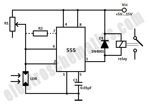
This light-activated relay circuit utilizes the 555 timer integrated circuit (IC) and a light-dependent resistor (LDR) to create a light-sensitive relay suitable for applications such as intruder alarm systems or automatic lamp control at sunset and sunrise. The potentiometer...

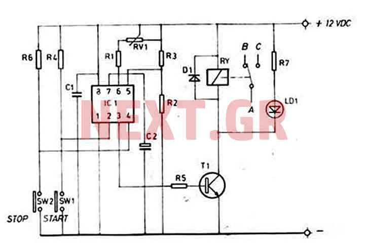
There have described the involvement benefited LM3909 circuit, which is quite expensive. That's why I prefer to use a much cheaper known timer 555th. Involvement of the tree is a very simple scheme is to figure 2. It is...
The threaded drive rod was constructed using standard 5/16 inch Whitworth threaded rod (18 TPI) due to availability, although M8 metric threading could have been an alternative. The radius of the curve in the drive rod, which must equal...
This water level alarm circuit can be utilized as a water level indicator to monitor the desired water level in various applications, such as tanks, swimming pools, or any location where water is stored. The circuit is constructed using...
This timer is ideal for small applications. Due to its simple structure, its usage and nevertheless its universal character, this mini timer is usable in the most current applications needing time intervals, from some seconds through approximately 60 minutes....
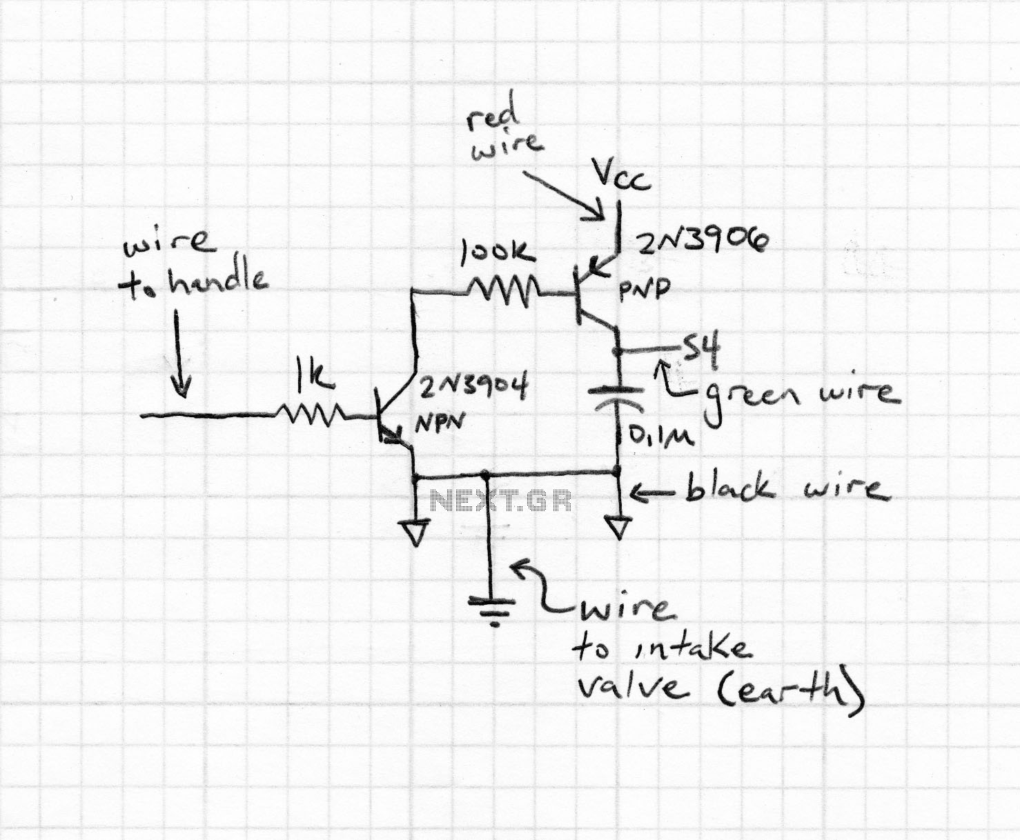
Wilf Rigter simplified this circuit a bit, made it phototropic, and doubled it up to yield a photopopper design in a post later the same day. I’ve got this design written up elsewhere in the library. The circuit described is...