
TICK TACK TOE LOGIC

Neon lamps are utilized in this circuit as visual indicators, representing the state of each position on the game board. When a player makes a move, the corresponding neon lamp illuminates, providing a clear visual cue of the current game state. The use of thyratrons in conjunction with relays forms a robust memory element that retains the game state and ensures that the sequence of moves adheres to the rules of the game.
The thyratron functions as a switching device that can handle high voltages and currents, making it suitable for this application. It is triggered by the input from the game board, allowing the circuit to remember the last move made by a player. The relay system further enhances this by controlling the flow of current to the neon lamps, ensuring that no player can make two consecutive moves. This is achieved through a carefully designed timing mechanism within the relay system, which enforces the turn-taking rules of the game.
The integration of these components creates a reliable and efficient electronic game board that not only provides an engaging user experience but also demonstrates fundamental principles of electronic logic and memory storage. The design exemplifies the application of basic electronic components in a practical scenario, showcasing their functionality in a game setting.Neon lamps serve as diode gates and indicate positions and moves on game board. Thyratron-relay com bination serves as memory, while relays referee sequence to prevent two successive moves by either player. -C. E. Hendrix and R. B. Purcell, Neon Lamp Logic Gates Play Tick-Tack-Toe, Electronics, 31:25, p 68-69. 🔗 External reference
Related Circuits
This logic probe uses a single CMOS IC and shows three logic conditions, High, Low and Pulsing. In addition if the probe input is neither hi or low (the high impedance state of tri-output logic ic`s) then no LED`s...
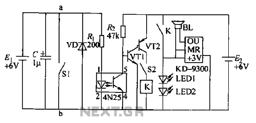
Due to the fast pace of modern life, intense competition, and widespread insomnia, which poses health risks, this section presents a feasible and effective method for controlling photoelectric hypnotic music to alleviate insomnia and facilitate sleep. The principle circuit...
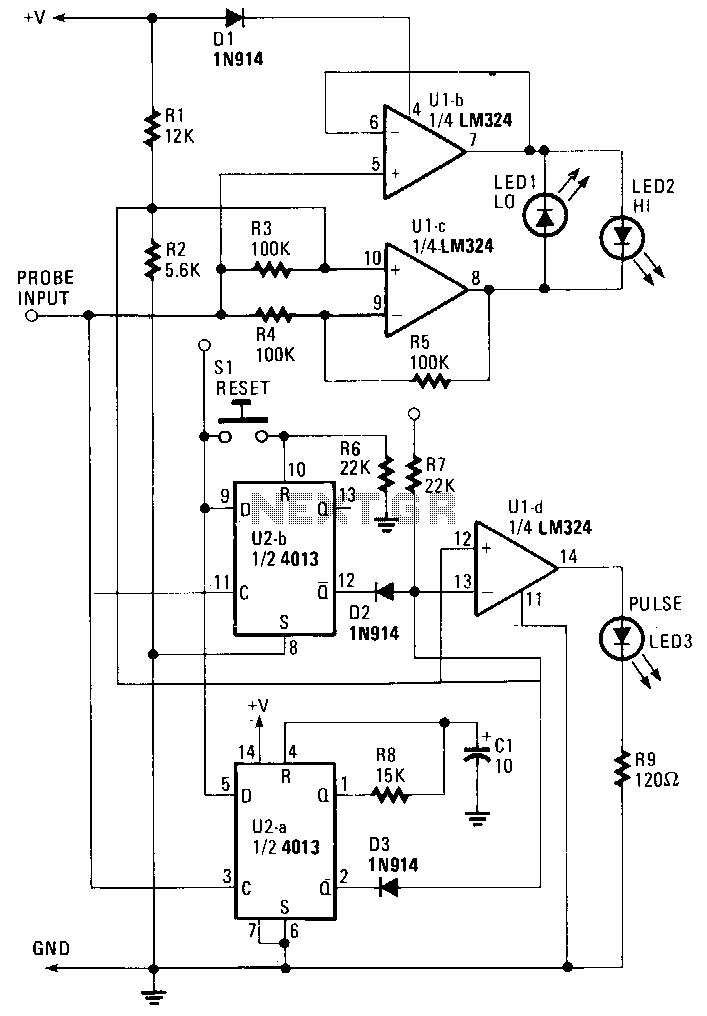
The probe operates using the power supply from the circuit under test (CUT). The input at the probe tip is divided into two pathways. One pathway directs the signal to the clock inputs of U2a and U2b. The other...
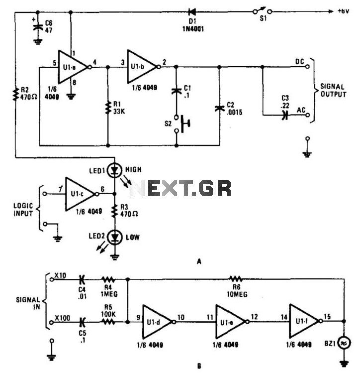
This circuit for a test set contains a signal injector (U1A/U1B) and associated components, a logic probe (U1C), and an audio amplifier. SI selects either 10-kHz or 100-Hz output. U1D, U1E, and U1F form an audio amplifier that drives...
Ideally, any testing equipment will not draw any current from the device under test. This ideal condition can be approximated by designing a testing device. To achieve the ideal condition where testing equipment does not draw current from the device...
When testing circuits with a logic probe, it is sometimes difficult to watch the LEDs on the probe to determine the logic state. With this probe, the logic states are audible. This probe is designed for TTL circuits only...