
Time Delay Relay

The time delay relay circuit consists of several key components that work together to provide a timed activation of the relay. The main elements include a resistor (R1), a capacitor (C1), and a switch (S1), which collectively form an RC timing circuit.
R1 serves as the timing resistor, and its value can be adjusted to modify the duration for which the relay remains activated. The time constant of the circuit, which determines the delay period, is influenced by the product of the resistance (R1) and the capacitance (C1). By selecting a suitable capacitor value for C1, the maximum on time can be tailored to meet specific requirements, allowing for flexibility in applications.
The switch S1 initiates the timing sequence. It can be a mechanical switch for manual activation or replaced with an NPN transistor for electronic triggering. This modification enables the circuit to be controlled by a microcontroller or another digital circuit, enhancing its versatility in automated systems.
Upon activation, the capacitor C1 begins to charge through R1. The relay will remain energized until the voltage across C1 reaches a certain threshold, at which point the relay will deactivate. The current capacity of the overall circuit is dictated by the specifications of the relay used; therefore, selecting a relay with appropriate ratings is crucial for ensuring the circuit can handle the intended load.
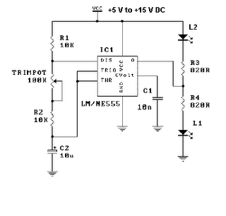
This time delay relay circuit is ideal for applications requiring a delayed response, such as in lighting control, motor activation, or any system where a timed action is necessary after an initial trigger. Proper design considerations should be taken into account to ensure that component ratings and values align with the desired operational parameters.A time delay relay is a relay that stays on for a certain amount of time once activated. This time delay relay is made up of a simple adjustable timer circuit which controls the actual relay. The time is adjustable from 0 to about 20 seconds with the parts specified. The current capacity of the circuit is only limited by what kind of relay you decide to use. # R1 adjusts the on time. # You can use a different capacitor for C1 to change the maximum on time. # S1 is used to activate the timing cycle. S1 can be replaced by a NPN transistor so that the circuit may be triggered by a computer, other circuit, 🔗 External reference
Related Circuits

In the 556 timer, the timing is determined by the charging rate of the external capacitor. For prolonged time delays, capacitors with extremely low leakage are necessary, which can be costly. The practicality of the components involved restricts the...
This is a simple LED flasher project that utilizes a common 555 timer integrated circuit (IC) for its operation. It is configured in astable mode, which means its output functions as a square wave oscillator. Two LEDs are connected...
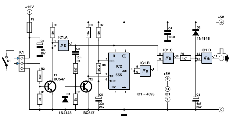
The circuit described here was designed as an addition to a remotely controlled garage door opener. The problem was that a brief burst of interference, arising from a thunderstorm or a mains spike, was enough to trigger the mechanism,...
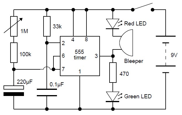
This adjustable analog timer circuit begins timing when it is activated. A green LED illuminates to indicate that the timing is in progress. Upon completion of the set time period, the green LED turns off, a red LED activates,...
This is a programmable clock timer circuit that utilizes individual LEDs to display hours and minutes. Twelve LEDs can be arranged in a circle to represent the twelve hours of a clock face, while an additional twelve LEDs can...
The cumulative timer circuit comprises resistor R1 and an internal crystal oscillator, represented in a chart. Resistors R1 and R2 are metal film types, while resistors R3 to R5 are rated at 1/8W and also of the metal film...