
Transistorized Auditory Gimmick

The described circuit operates as a voltage-controlled oscillator (VCO) designed for reading transmitter meters, particularly useful in applications for the visually impaired. The key component, the NPN germanium transistor, is critical for achieving low base bias, which is essential for the circuit's operation. The blocking oscillator configuration is employed to generate the necessary oscillations, and the transformer plays a vital role in facilitating the push-pull output, which was common in older transistor radios.
The circuit's design ensures that the output can drive a small speaker, providing audible feedback that can be interpreted by the user. The careful selection of components, including the capacitors and resistors, allows for adjustments in loudness and sensitivity, making the circuit adaptable to various input conditions.
The use of a toroidal coil in the RF section indicates an effort to minimize inductance while maximizing the efficiency of the RF current sensing. The inclusion of a small-signal diode and sensitivity control further enhances the circuit's ability to provide accurate readings, ensuring that the user can discern small changes in the input signal.
Overall, the circuit's simplicity, combined with its effective use of basic electronic components, allows for a practical solution in applications where visual meter readings are not feasible. The design principles laid out by Gunderson continue to influence adaptive technologies, demonstrating the enduring relevance of this early work in the field of electronics.(This circuit first appeared in "The Braille Technical Press", edited by Robert W. Gunderson, in 1955. Gunderson, W2JIO, designed this "gimmick" to read transmitter meters. It appeared many times since over a 20-year period, included even in commercial aids and appliances for the blind. Bill Gerrey, et al, has never gotten around to generating a p rint schematic diagram of the "gimmick" by itself, although it has been part of Smith-Kettlewell adaptive instruments of various sorts over another 30-year span; its circuit appears in those published designs. ) Key components of this VCO are: A hard-to-find NPN germanium transistor (needed for its beta at very low base bias -even though it is non-linear in this service).
The transformer is for push-pull output in transistor radios of Yesteryear, but for the time being, many still exist in surplus (even from Radio Shack, 270-1380). The circuit uses a "blocking oscillator", which requires a center-tapped primary winding - specified impedances from 500 to 25, 000 ohms, (center tapped) are appropriate.
The transformer secondary winding drives a small speaker; here again, the rated impedance (3. 2 to 16 ohms) is not critical, even though the speaker may be rated at 8 ohms. The center tap of the primary goes to the emitter of a PNP small-signal transistor (type not critical; a 2N2907 was used here). The full primary winding is shunted by 0. 022uF (which increases the loudness). One end of the primary goes through 0. 022uF to the base of the PNP transistor. The other end of the primary winding goes through an SPST on/off switch to the positive of the battery.
The collector of the transistor is grounded, as is the negative of the battery. The base of the PNP transistor goes through 22 K ohms to the collector of an NPN germanium transistor (2N388 used here; 2N35 was a traditional type number). The emitter of the NPN unit is grounded. Its base is the hot input; the cold side of the input is grounded. Caution! This input going directly to the base means that any input signal exceeding the knee of the base-emitter junction will burn it out.
Moreover, the lower range of the VCO is best exploited when the impedance of the source, typically a d`Arsenval meter, is low - under 10, 000 ohms. Thus, care must be taken to assure that any input signal not exceed 0. 3 volts. The base of the NPN is bypassed to ground by 0. 01uF. This base goes through a 2. 2mH RF choke to the positive side of a millimeter to be read. The meter side of the choke is also bypassed to ground by 0. 01uF. It is assumed that the negative side of the meter is at ground, the cold input. If not, the gimmick may be floating, properly insulating it and its battery, made common only to the meter.
(The following circuit is that of a meter board in the MFJ "Artificial Ground". It can be used anywhere that an RF current is to drive a relative indicator. ) A toroidal coil of unknown specifications has a wire carrying RF current running through its center. The bottom end of this coil is grounded. The coil is shunted by a 1K 3-watt resistor (3-watt rating only needed if transmitter power is high).
The top of the coil goes to the anode of a small-signal diode, with the cathode going to the clockwise end of a 10K sensitivity control. The counterclockwise end of this control is grounded. The control is shunted by 0. 01uf. The wiper of the control goes through the 100 microamp meter to ground. If only the gimmick is connected between the wiper and ground, smoother operation of the control will be had if a 1.
2K resistor, substituting for the meter, goes from the wiper to ground. The 1955 circuit by Robert Gunderson is crude but very effective when connected across a visual meter whose relative indications are important to note. Only changes in pitch are required in a grid-dip meter or an antenna bridge where a "dip" in the meter reading is all that is to be noted.
🔗 External reference
Related Circuits

Transistors Q1 and Q2 are configured as a free-running multivibrator. The output at the emitter of Q2 drives the base of the common emitter amplifier Q3, which controls the lamp. This circuit configuration allows for independent variation of flash...
The schematic illustrates a standard AM radio circuit utilizing NPN transistors. This generic circuit does not provide specific values for all components, serving instead as a reference point for experimenters to begin their projects. The schematic of a typical transistor...
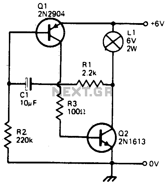
This simple circuit will flash a 6-volt lamp at a rate determined by the size of capacitor C1. It is most economical on power as it only draws current when the lamp is on. When the lamp is off,...
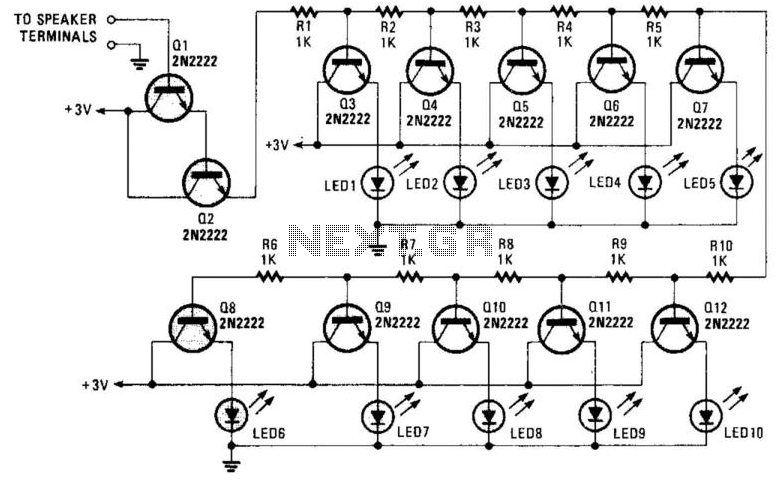
A resistor network (R1 through R10) with emitter followers (Q1 and Q2) drives LED drivers (Q3 through Q7). This circuit was utilized as a "light organ" to provide visual volume indication. It can be connected to a speaker, another...
If two of these circuits are made in the same enclosure for stereo, then there can be a single power supply to run both of them. There should be a resistor in series with the incoming 9V+ lead so...

A schematic of a typical transistor AM radio is presented. This circuit utilizes npn transistors. It is a generic circuit; hence, specific values for some components are not provided. This circuit serves as a reference point for experimenters. The schematic...