
Tunable frequency oscillators

The variable oscillator circuit is designed to generate oscillating signals with adjustable frequency characteristics. At the core of this circuit is the timing capacitor (CT), which plays a crucial role in determining the oscillation frequency. The active elements, typically comprising transistors or operational amplifiers, are responsible for the rapid discharge of the timing capacitor, allowing the circuit to reset and initiate a new cycle of oscillation.
In the configuration shown in Fig. 66-7A, the discharge path for the timing capacitor is facilitated through a controlled mechanism that ensures precise timing intervals. The active components are configured to switch states at specific voltage thresholds, effectively controlling the timing capacitor's discharge rate. This results in a variable frequency output that can be fine-tuned for various applications.
Fig. 66-7B introduces an alternative method for achieving similar oscillation characteristics. This may involve different arrangements of the active elements or additional passive components, such as resistors and inductors, to modify the discharge path or timing characteristics. The choice of method depends on the desired performance specifications, including stability, frequency range, and power consumption.
Overall, the design of the variable oscillator circuit is critical for applications in signal generation, modulation, and timing functions across various electronic systems. The ability to adjust the frequency dynamically makes it a versatile component in both analog and digital circuits.The variable oscillator circuit includes active elements for discharging the timing capacitor CT shown in Fig. 66-7A. A second method is given as in Fig. 66-7B,
Related Circuits
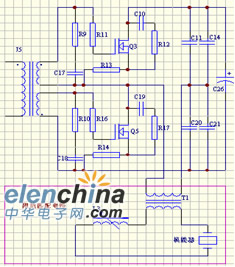
Ultrasonic cleaning primarily relies on the phenomenon of ultrasonic cavitation. In the presence of a sound field, liquid bubbles undergo high-frequency micro-vibrations. When the sound pressure reaches a specific threshold, air bubbles grow rapidly and then collapse suddenly, creating...
Another application of the frequency-to-voltage converter (FVC) is as a tone or frequency decoder. This circuit is utilized to identify the frequency band of an oscillation. The frequency-to-voltage converter (FVC) serves as an essential component in various electronic applications, particularly...
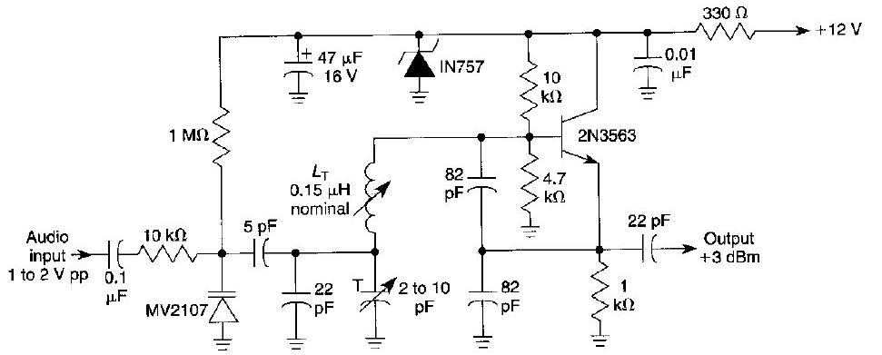
This FM oscillator can be utilized for wireless audio, microphone, and part-15 applications where a stable frequency-modulated oscillator is required. The FM oscillator is an essential component in various communication systems, particularly in wireless audio transmission and microphone applications. It...
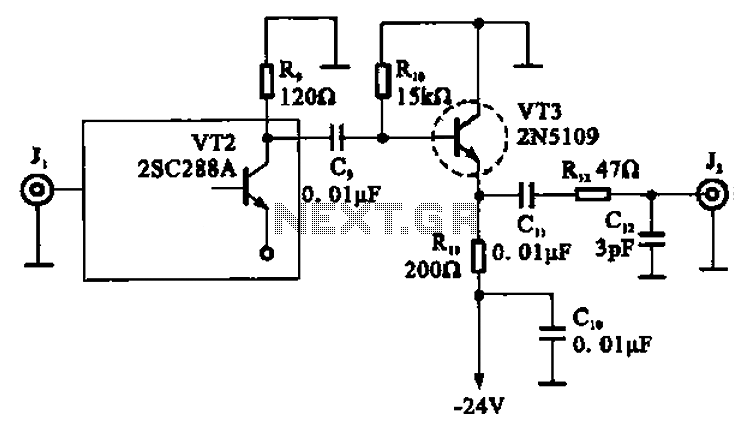
A high-frequency signal is displayed in the output amplifier. The circuit consists of a VI3 common collector amplifier (emitter follower) designed to enhance the child-band. It is a high-frequency amplifier (1-250 MHz) that increases the output voltage and boosts...
An oscillator can be constructed using an LC (inductor-capacitor) tank circuit. By varying the capacitance of the capacitor in the LC tank circuit, the frequency of the oscillator can be adjusted. An LC tank circuit serves as a fundamental building...
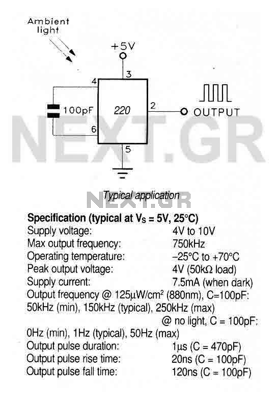
A large area photodiode and current-to-frequency converter integrated into a clear plastic 8-pin DIL package. The output generates a pulse train whose frequency is directly proportional to the light intensity. It is CMOS compatible (a 3.3kΩ pulldown resistor is...