
Tunable IF with TDA7000
This circuit represents a modified receiver design that has undergone various iterations to enhance its functionality, particularly by integrating a frequency indicator system. The original circuit, while operational, prompted a series of modifications aimed at improving user feedback regarding frequency reception. The choice to utilize a FET (Field-Effect Transistor) buffer amplifier indicates a focus on maintaining signal integrity while interfacing with the oscillator coil.
The FET buffer amplifier serves to isolate the oscillator from the load, ensuring that the signal remains stable and free from distortion. This is particularly important in RF (radio frequency) applications where signal fidelity is crucial. The signal taken from the oscillator coil is indicative of the frequency being received, which can be crucial for tuning the receiver to specific satellites or frequencies.
The left RCA plug mentioned in the description likely serves as an output for the modified frequency indicator, allowing for external monitoring or interfacing with other devices. The modifications, while numerous, reflect an iterative design process where each version aimed to improve the circuit's performance. However, the final conclusion drawn from the modifications indicates that the inherent stability of the oscillator was sufficient for operation without the need for complex indicator systems.
The mention of a simple system with preset resistors for each desired satellite suggests a pragmatic approach to tuning, where each preset corresponds to a specific frequency. This method simplifies the user experience by allowing quick access to frequently used frequencies without the need for extensive adjustments.
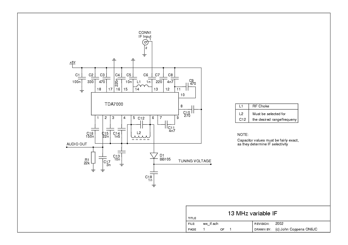
Overall, the circuit exemplifies the balance between complexity and functionality in electronic design, demonstrating how iterative modifications can lead to a more user-friendly and effective device while maintaining the core operational integrity of the original design.This circuit has `suffered` a lot of modifications over its long life... Even the lettering on the integrated circuit was partially erased of the years. The main motive of the mods was not that the circuit didn`t work right, but were several tries to add some kind of frequency indicator to the receiver. The left RCA plug and associated components are witnesses to the last version, adding a FET buffer amplifiera and taking signal from the oscillator coil.
None of the indicator systems was satisfactory, and the actual stability of the receiver oscillator was so good that it wasn`t really necessary either. A simple system with a preset resistor for each of the the desired satellites was more than enough 🔗 External reference
Related Circuits
This is a very simple crystal receiver circuit for short wave band and can be used with headphones. The described circuit is a basic crystal receiver designed to operate within the shortwave frequency band. The primary components of this circuit...

With the P1 we regulate the intensity of sound. With the P2 we regulate the frequency of reception. Optionally: If you want to check the frequency with your PC it will be supposed you make the following energies: You...
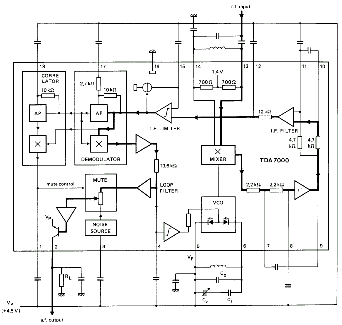
GENERAL DESCRIPTION The TDA7000 is a monolithic integrated circuit designed for mono FM portable radios or receivers, emphasizing minimal peripheral components to achieve compact dimensions and reduced costs. This integrated circuit features a Frequency-Locked-Loop (FLL) system with an intermediate...
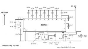
The following circuit illustrates a Single Chip FM Radio Circuit. This circuit is based on the IC TDA 7000 or TDA 7400. Features include a low-cost FM radio circuit. The Single Chip FM Radio Circuit utilizing the TDA 7000 or...
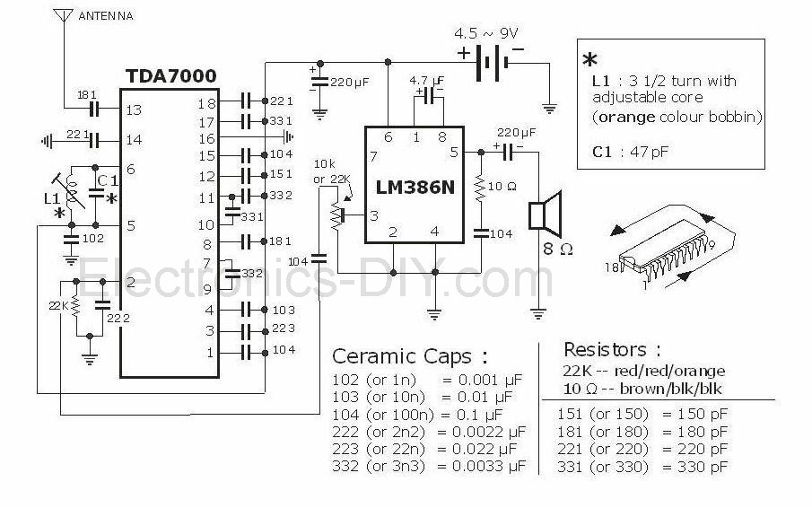
This project is an FM radio utilizing the TDA7000 and LM386 integrated circuits. The TDA7000 IC is notable for its operation as a complete FM superheterodyne receiver, incorporating the standard components such as a local oscillator, mixer, intermediate frequency...
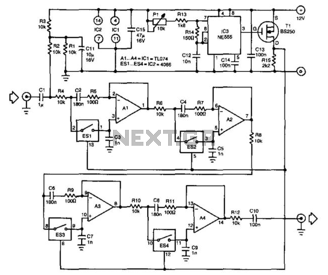
One of the challenges in designing higher-order tunable bandpass filters is achieving proper tracking of the variable resistors in the RC networks. The implementation of switched capacitor networks can resolve this issue, as demonstrated in this filter. The filter...