
Tunable notch filter to suppress hum

The described narrow stop-band filter is designed to eliminate specific frequency components from an input signal, particularly targeting power-line hum, which often manifests at 60 Hz (or 50 Hz in some regions). The filter's adjustable notch allows for fine-tuning, accommodating variations in the frequency of unwanted signals, making it versatile for various applications.
The circuit typically consists of a combination of resistors, capacitors, and a potentiometer. The potentiometer serves as a variable resistor that alters the filter's characteristics, allowing the user to set the notch frequency precisely within the specified range of 45 to 90 Hz. This adjustability is crucial for applications where the exact frequency of interference may vary.
The filter's design may employ a second-order or higher-order topology to achieve the desired attenuation level of at least 30 dB. This level of attenuation is significant enough to reduce the impact of noise on sensitive audio equipment or other electronic devices.
The use of wide-tolerance components contributes to the overall affordability of the circuit. While high-precision components can offer better performance, they often come at a higher cost. By utilizing components with wider tolerances, the circuit can maintain a balance between performance and cost-effectiveness, making it accessible for hobbyists and professionals alike.
In summary, this narrow stop-band filter is a practical solution for mitigating unwanted frequency interference, particularly from power-line sources, while remaining economical and easy to implement in various electronic projects.This narrow-stop-band filter can be tuned by the pot to place the notch at any frequency from 45 to 90 Hz. It attenuates power-line hum or other unwanted signals by at least 30 dB Because the circuit uses wide-tolerance parts, it is inexpensive to build.
Related Circuits
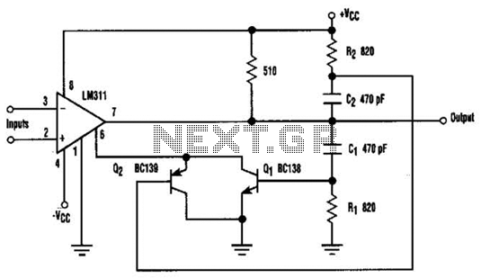
When the comparator's output transitions from low to high, the rising edge of the output pulse, differentiated by the Cl/Rl chain, activates Ql. This action blocks the comparator via its strobing input and maintains its output state for a...
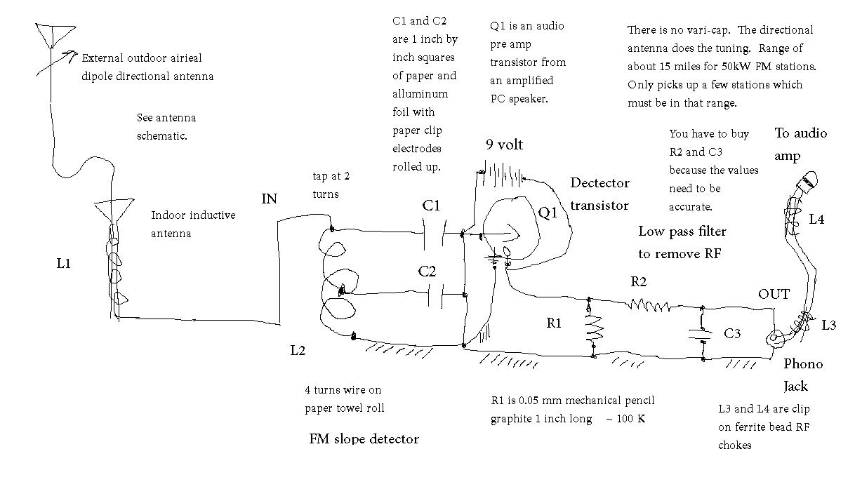
Seeking the appropriate resistor and capacitor values for a low-pass filter designed to eliminate radio frequency (RF) interference. The application focuses on filtering out unwanted untuned RF signals from a crystal radio set. A low-pass filter is an essential component...
One application of this handy circuit is a graphic equalizer, created by feeding a signal to a number of parallel band-pass filters each tuned to a different frequency; typically octaves apart. Then, you can adjust the strength in each...
Prototype 2 utilizes a common base to control various elements. This iteration includes a button that activates the tone only when pressed, along with a rotary potentiometer for volume adjustment. The circuit incorporates an Analog Devices ADXL3xx accelerometer that...
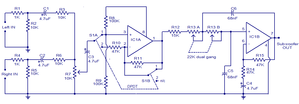
The circuit diagram depicts a simple subwoofer filter that operates on a 12V DC supply, making it particularly useful for automobile subwoofer applications. This circuit functions as a low-pass filter, with an adjustable pass frequency ranging from 60 to...
A simple circuit, High-Pass filter, variable between frequencies 20HZ until 200HZ, useful in a lot of cases elaboration of sound signals. The regulation is achieved with the double potesometer 47K? and the frequency response in his two extreme places,...