
1-Transistor FM Transmitter

The 1-transistor FM transmitter is a compact electronic circuit designed to transmit audio signals over a short range using frequency modulation. The circuit primarily consists of passive components such as resistors, capacitors, and an inductor, along with a single transistor that serves as the active amplification element.
The resistors R1, R2, R3, and R4 play crucial roles in setting the biasing conditions for the transistor and controlling the gain of the circuit. Specifically, R1 (27kΩ) and R2 (56kΩ) form a voltage divider that establishes the base bias voltage, ensuring the transistor operates in its active region. R3 (12kΩ) and R4 (100Ω) are used to stabilize the operating point and limit the collector current, respectively.
Capacitors C1 (1μF), C2, and C3 (both 470pF) are used for coupling and bypassing purposes. C1 couples the audio input signal to the base of the transistor, allowing the audio signal to modulate the carrier frequency. C2 and C3 help filter high-frequency noise, ensuring the transmitter operates efficiently and produces a clean output signal.
C4, with a variable capacitance of 6 to 10pF, acts as a tuning capacitor that adjusts the resonant frequency of the circuit along with inductor L1. This tuning capability allows users to select the desired frequency for transmission. C5, a trimmer capacitor with a variable range of 1 to 30pF, is utilized for fine-tuning the output frequency, providing flexibility in achieving optimal performance.
Inductor L1 is typically etched on the PCB, which simplifies the design and minimizes the footprint of the circuit. The inductor, in combination with the capacitors, forms a tank circuit that determines the oscillation frequency of the transmitter.
Overall, this 1-transistor FM transmitter circuit is a simple yet effective design suitable for various applications, including hobbyist projects and educational demonstrations. Its compact size and ease of assembly make it an attractive option for those looking to explore the fundamentals of radio frequency transmission.1-Transistor FM Transmitter. R1 27k R2 56k R3 12k R4 100 C1 1u C2, C3 470p C4 6 to 10p C5 1-30p trimmer L1 etched on PCB or a. 🔗 External reference
Related Circuits
The FM Wireless Microphone has gained popularity among both beginners and experienced constructors. It has been utilized in guitars and as a component of remote control systems. There have been numerous requests for a higher-powered circuit with improved microphone...
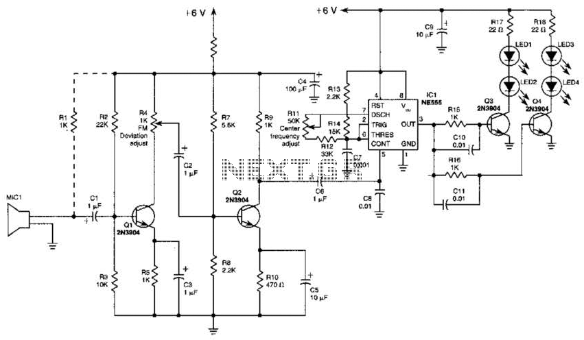
This transmitter employs a two-stage amplifier configuration using transistors Q1 and Q2 to frequency modulate an NE555 timer, which is set up as a voltage-controlled oscillator (VCO) operating at approximately 50 kHz. The resulting frequency-modulated pulse train is transformed...
Here is a simple schematic of a TV transmitter circuit, or video transmitter circuit, capable of broadcasting in the VHF range from 60 to 200 MHz. The input video source can be any CCD camera or VCR. The output...
This application note provides a concise overview of power amplifier theory and presents simulation results that offer insights into the operation of the power amplifier across all of MAXIM's LFRF transmitters and transceivers. Power amplifiers are critical components in communication...
This circuit utilizes a 74HC14 hex Schmitt trigger inverter as a square wave oscillator to drive a small signal transistor configured in a class C amplifier. The oscillator frequency can be set to a fixed value using a crystal...
L1 is 0.112uH (this tunes to the middle of the FM band, 98 MHz, with VC1 at its centre value of 33pF). L1 is 5 turns of 22 swg enamelled copper wire close-wound on a 5mm (3/16") diameter former....