
UHF TV Antenna Booster

The UHF band TV antenna booster circuit is designed to amplify weak signals received by UHF antennas, thereby improving the overall quality of the television reception. The circuit utilizes the BF180 transistor, which is known for its high-frequency performance and low noise characteristics, making it suitable for applications in UHF amplification.
The circuit begins with a band-pass filter, which is crucial for eliminating unwanted frequencies while allowing the desired UHF signals to pass through. This filter is typically composed of inductors and capacitors arranged in a configuration that sets the cutoff frequencies. The design of the filter is essential, as it directly influences the performance of the booster by determining the bandwidth and selectivity of the signals being amplified.
Following the band-pass filter, the BF180 transistor is configured in a common-emitter arrangement to provide voltage gain. The transistor is biased correctly to operate in its active region, ensuring linear amplification of the incoming signal. The gain of 15dB indicates that the output signal will be significantly stronger than the input, which is beneficial for overcoming losses that may occur due to cable connections or other environmental factors.
Power supply considerations are also crucial in this circuit. A stable DC voltage is required to power the transistor, and capacitors may be used to filter out any noise from the power supply, ensuring that the amplifier operates efficiently and without distortion.
Overall, this UHF band TV antenna booster circuit is an effective solution for enhancing television signal reception in areas where signal strength is weak, and its simplicity makes it accessible for hobbyists and professionals alike. Proper assembly and component selection will ensure that the circuit performs optimally, delivering improved signal clarity and quality for UHF television broadcasts.This is the circuit diagram of UHF band TV antenna booster with 15dB gain power. This low cost antenna booster is simple and easy to build. This circuit formed based on BF180 UHF Transistor. The first stage is an band pass filter constructe.. 🔗 External reference
Related Circuits
Please find attached your copy of my four foot unamplified box loop. It will tune from 525 kHz to about 1710 kHz covering the entire Broadcast Band. The umbrella stand described in the article is the type you would...
Results are displayed on an analog VSWR meter. The design was originally published in Break-In, New Zealand's amateur radio magazine in September/October 2005, and is republished here with the editor's permission. Note: Break-In is a term used in amateur...
There are extremely wideband software-defined radios (SDR) where a wideband antenna is a natural choice. Wideband small magnetic loops (WSM loops) have been used for 3-4 decades, and their effectiveness as a wideband SDR input is under evaluation. The...
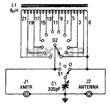
This antenna tuner is designed for low-power transmitters or shortwave receivers with a maximum power output of 5 watts. The switch S2 is used to select the inductance, while S1 connects a 365-pF capacitor either to the transmitter or...
A ground loop in your AV system caused by antenna connection or TV cable is very common if you have your computer connected to the same system. This type of ground loop problem can be solved by using suitable...

This is a design circuit for a low-cost FM antenna booster that can be used to listen to programs from distant FM stations clearly. The antenna FM booster circuit comprises a common-emitter tuned RF preamplifier wired around the VHF/UHF...