
Ultrasonic Proximity Detector

The ultrasonic proximity detector circuit operates by emitting ultrasonic waves through the paired piezo-ceramic transducers. The circuit is designed to measure the time it takes for the emitted waves to reflect off nearby objects and return to the transducers. The operational amplifier processes the signals received from the transducers, enabling the detection of proximity based on the time delay of the reflected waves.
Key components include the micropower operational amplifier, which ensures low power consumption, making the circuit suitable for battery-operated applications. The matched piezo-ceramic transducers are critical for generating and receiving the ultrasonic signals, ensuring that the emitted frequency is consistent and optimized for detecting nearby objects.
The circuit's design may also incorporate additional elements such as resistors and capacitors to filter the signal and improve sensitivity. The output can be connected to an indicator, such as an LED or a buzzer, to provide a visual or audible alert when an object is detected within a specified range. This makes the ultrasonic proximity detector ideal for applications in robotics, automotive systems, and security devices, where distance measurement and object detection are essential.
Overall, this circuit exemplifies a practical application of ultrasonic technology, leveraging simple components to achieve effective proximity sensing.This is ultrasonic proximity detector circuit. This circuit consist of micropower opamp and a pair of matched piezo-ceramic tranducers. It uses a 9V battery as.. 🔗 External reference
Related Circuits
A while ago I got an email asking for the schematic of a circuit to detect cut phone lines. It didn’t take me long to find this circuit in Electronics Now. When the circuit detects that a phone line...

Inverters U1a and U1b are connected in a simple RC oscillator circuit. The frequency is determined by the values of R1, C1, C2 and the internal characteristics of the integrated circuit. As long as the circuit is oscillating, a...
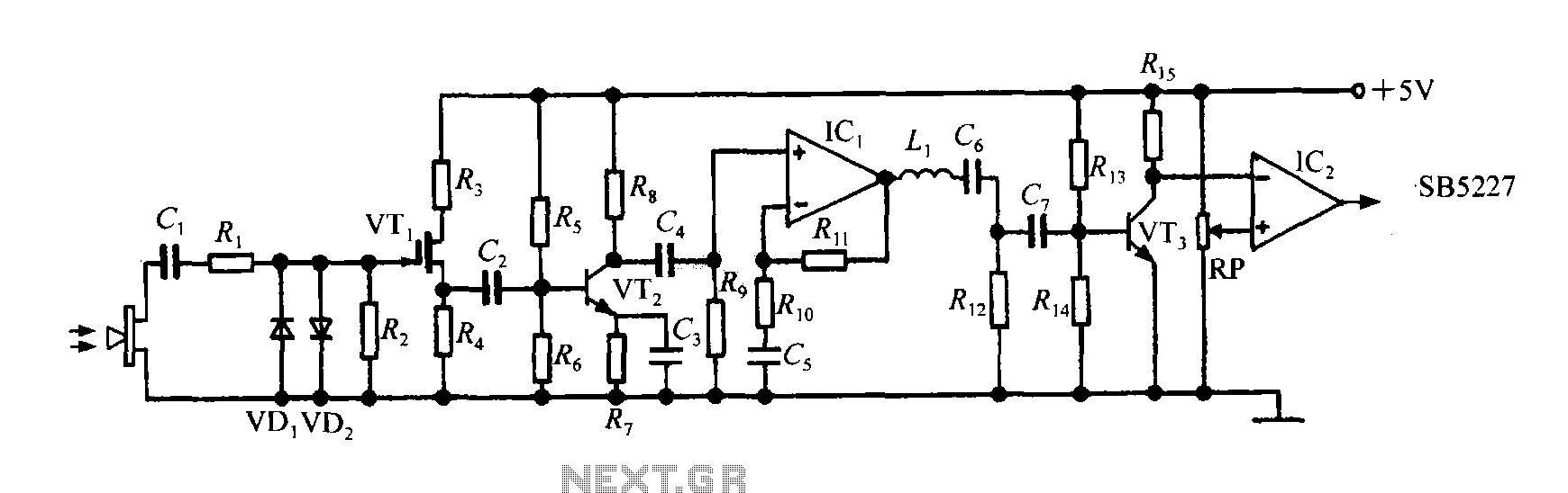
The SB5227 ultrasonic signal output is very weak and must be amplified via a power amplifier for effective transmission. A typical transmission circuit is illustrated in the accompanying figure. The SB5227 ultrasonic signal is sourced from output pin 10,...

This is an Overheat Detector Alarm Switch using the Temperature Sensor IC LM35. The core of this overheat detector (fire alarm) circuit is a precision integrated temperature sensor, the LM35 (IC1), which provides an accurately linear and directly proportional...
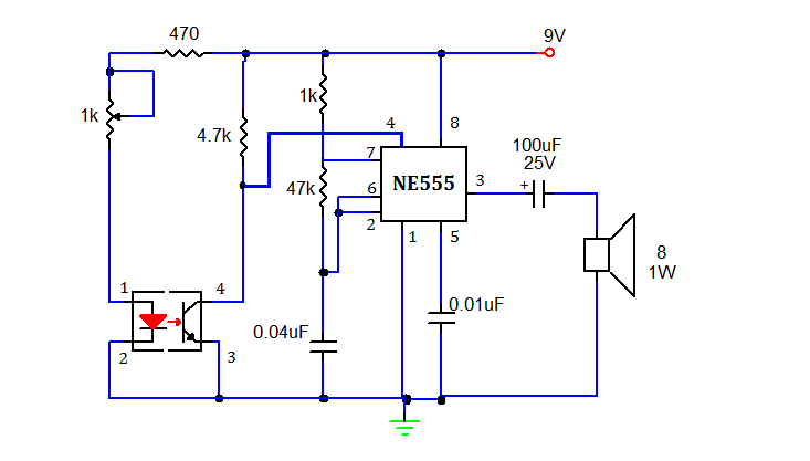
This document presents a simple smoke sensing alarm circuit utilizing a 555 timer. The circuit is designed to detect smoke and trigger an alarm when the air is contaminated. The components employed in this design include an astable multivibrator...

The metal detector project is designed for detecting metallic objects by sensing variations in high-frequency eddy current losses. It employs an externally-tuned circuit that functions as oscillators. The output signal level is modified by the presence of an approaching...