
Ultrasonic Proximity Detector Electrical Project

The Ultrasonic Proximity Detector is an electronic device that utilizes ultrasonic waves to detect the presence of objects within a specified range. The primary components of this detector include an ultrasonic transducer, a microcontroller, and a signal processing unit. The transducer emits ultrasonic pulses that reflect off nearby objects, and the time taken for the echoes to return is measured to determine the distance to the object.
In the circuit design for the Ultrasonic Proximity Detector, the ultrasonic transducer is typically connected to a microcontroller that manages the timing of pulse emission and the reception of echoes. The microcontroller processes the received signals to calculate distances based on the speed of sound in air. The current-to-voltage converter is used to translate the received echo signals into a usable voltage level for the microcontroller, while the voltage-to-current converter may be included to drive additional components or indicators, such as LEDs or alarms, based on the detected proximity of objects.
The Printed Circuit Board (P.C.B.) design is crucial for the reliable operation of the Ultrasonic Proximity Detector. The P.C.B. layout must account for the placement of the transducer, ensuring that it is positioned for optimal signal transmission and reception. Additionally, careful routing of traces is necessary to minimize interference and maintain signal integrity. The report outlines the complete procedure for fabricating the P.C.B., including the selection of materials, etching processes, and soldering techniques.
Overall, this vocational training report provides a comprehensive overview of the Ultrasonic Proximity Detector and its associated electronic components, offering valuable insights into practical applications in the field of electrical engineering.This is a vocational training report on Ultrasonic Proximity Detector undertaken under at Bharat Heavy Electrical Limited (BHEL)in partial fulfillment of the requirement for the Bachelor in Electrical engineering. The report covers topics like Making Printed Circuit Board (P. C. B. ) with full procedure, current-to-voltage convertor, voltage-to-curre nt converter, ultrasonic proximity detector and its working. You can also Subscribe to FINAL YEAR PROJECT`S by Email for more such projects and seminar. 🔗 External reference
Related Circuits

The circuit utilizes a dual operational amplifier integrated circuit (IC), specifically the 1458, which contains two separate op-amps within a single package. In this configuration, the first op-amp functions as a voltage follower, directing its output to charge capacitor...
This circuit will automatically switch on several mains-powered "slave" loads when a "master" load is turned on. For example, it will switch on the amplifier and CD player in a stereo system when the receiver is turned on. It...
A loop antenna can greatly improve medium wave reception. Loop antennas are directional and receive signals along the plane of the windings. The directional quality improves signal to noise ratio of the desired signal while rejecting signals perpendicular to...
The drawings and photos below are for an operating incline railway that was built by the London Model Railroad Group for its O scale model railway club located at London, Ontario, Canada. This is a single car model loosely...
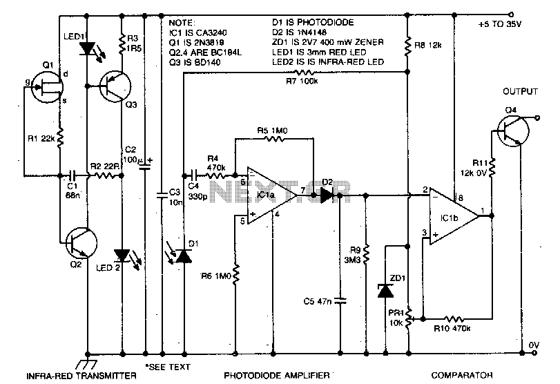
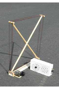
The proximity sensor operates on the principle of emitting a beam of modulated infrared light from the LED2 emitter diode and detecting reflections from objects that come into the path of the beam using a photodiode detector, Dl. The...
This simple circuit can be utilized to activate various devices, such as connecting it to microcontrollers, relays, secret alarms, or robot applications. It can also be used to turn on LED1, which remains lit as long as the metal...