
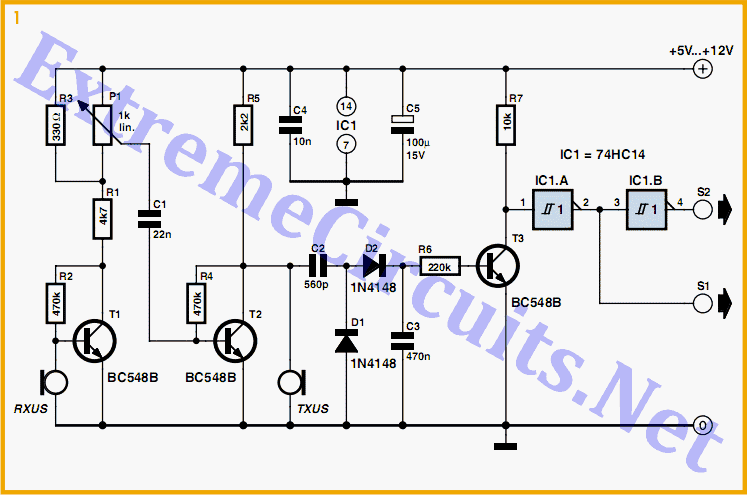
Ultrasonic Radar

The ultrasonic radar circuit is designed to enhance security by detecting motion through ultrasonic waves. The core components include piezoelectric transducers, which are essential for transmitting and receiving ultrasonic signals. The transmitter's multivibrator configuration, created using NAND gates, allows for a stable oscillation at the desired frequency, which can be fine-tuned using the trimmer potentiometer P2. This adjustment is crucial for ensuring that the transmitter's frequency aligns with the natural resonance of the transducers, maximizing energy transfer and sensitivity.
In the receiver section, the captured ultrasonic signals are amplified to ensure that even faint reflections are processed effectively. The use of a 741 op-amp in conjunction with a transistor (TR3) provides a reliable amplification stage, enabling the detection of subtle changes caused by movement. The feedback mechanism through IC2, adjustable via P1, allows for fine-tuning of the circuit's sensitivity, ensuring that only significant disturbances trigger the alarm.
The Schmitt trigger configuration adds hysteresis to the system, preventing false alarms due to minor fluctuations in the received signal. This stability is vital in environments where external noise may interfere with the ultrasonic signals. The output transistors TR1 and TR2 are responsible for driving the alarm system or relay, providing a clear indication of detected motion.
The power supply requirements of 9-12 VDC make this circuit versatile, allowing it to be powered by various sources, including batteries, which is particularly useful for portable applications. Overall, this ultrasonic radar circuit represents a sophisticated yet practical solution for enhancing security in various settings.It is very interesting project with many practical applications in security and alarm systems for homes, shops and cars. It consists of a set of ultrasonic receiver and transmitter which operate at the same frequency. This is a one design circuit for the ultrasonic radar circuit. Here`s the figure of the circuit; As it has already been stated the circuit consists of an ultrasonic transmitter and a receiver both of which work at the same frequency. They use ultrasonic piezoelectric transducers as output and input devices respectively and their frequency of operation is determined by the particular devices in use.
The transmitter is built around two NAND gates of the four found in IC3 which are used here wired as inverters and in the particular circuit they form a multi vibrator the output of which drives the transducer. The trimmer P2 adjusts the output frequency of the transmitter and for greater efficiency it should be made the same as the frequency of resonance of the transducers in use.
The receiver similarly uses a transducer to receive the signals that are reflected back to it the output of which is amplified by the transistor TR3, and IC1 which is a 741 op-amp. The output of IC1 is taken to the non inverting input of IC2 the amplification factor of which is adjusted by means of P1.
The circuit is adjusted in such a way as to stay in balance as long the same as the output frequency of the transmitter. If there is some movement in the area covered by the ultrasonic emission the signal that is reflected back to the receiver becomes distorted and the circuit is thrown out of balance.
The output of IC2 changes abruptly and the Schmitt trigger circuit which is built around the remaining two gates in IC3 is triggered. This drives the output transistors TR1, 2 which in turn give a signal to the alarm system or if there is a relay connected to the circuit, in series with the collector of TR1, it becomes activated.
The circuit works from 9-12 VDC and can be used with batteries or a power supply. 🔗 External reference
Related Circuits
The first sensor that a robot is typically equipped with is an obstacle detector. It can take three different forms, depending on the type of obstacle to be detected. Obstacle detectors are essential components in robotic systems, designed to enhance...
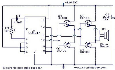
The circuit diagram of an ultrasonic mosquito repeller is presented. This circuit operates on the principle that sound frequencies in the ultrasonic range, above 20 kHz, can repel insects such as mosquitoes. It utilizes a Phase-Locked Loop (PLL) integrated...
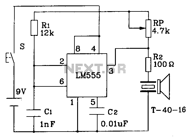
The circuit operates at a distance of 3 feet from the oscillating pulse output of a 555 timer generating a 40kHz signal, driving a T-40-16 transducer to emit ultrasonic signals at the same frequency. The circuit is powered by...
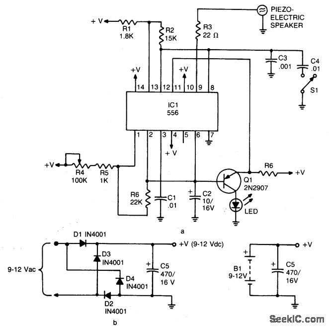
The device emits ultrasonic sound waves that sweep between 65,000 and 25,000 hertz. It is designed around a 556 dual timer, where one half operates as an astable multivibrator with an adjustable frequency of 1 to 3 Hz. The...
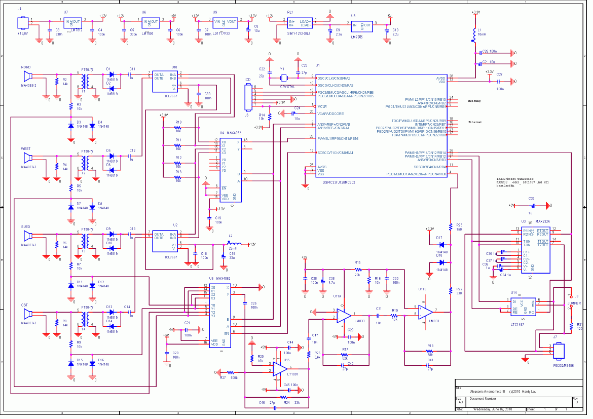
This ultrasonic anemometer is designed for the two-dimensional measurement of horizontal wind speed components and wind direction, as well as virtual temperature. Due to its high measurement rate, the device effectively captures gusts and peak values without delay. The...
I have found this circuit to have better sensitivity, both in distance to a visible bat and in audio frequency, than some other published circuits using a 40kHz transducer with 4000x gain amplification, though the 40kHz transducer I used...