
ULTRASONIC RECEIVER

The 4046 Phase-Locked Loop (PLL) is a versatile device that integrates a voltage-controlled oscillator, phase comparator, and other essential components, making it ideal for applications in ultrasonic detection. The piezo speaker (SPKR1) acts as a transducer, converting ultrasonic waves into electrical signals. The initial amplification stages, provided by transistors Q1 and Q2, ensure that the weak signals received are sufficiently boosted for further processing.
At the heart of the system is the phase comparator within the 4046 IC, which compares the frequency of the incoming signal from SPKR1 with the frequency generated by the VCO. Adjusting the potentiometer R9 allows for fine-tuning of the VCO frequency, enabling the system to respond to various ultrasonic frequencies. The output from the phase comparator, which represents the frequency difference between the incoming and VCO signals, is critical for generating audible tones corresponding to the detected ultrasonic frequencies.
The amplified difference signal is further processed by transistor Q3, which increases the power level before it is coupled through transformer T1. This transformer serves to isolate the circuit and match the impedance for optimal audio output in the headphones. The range of frequencies that can be detected, from 12 kHz to over 42 kHz, provides flexibility in applications, whether for ultrasonic sound detection or Morse code transmission. This design is particularly useful in environments where conventional sound detection methods are ineffective, allowing for innovative communication and detection capabilities in ultrasonic ranges.The 4046 PPL is used as the heart of a tunable ultrasonic receiver that can be used to locate unheard ultrasonic sounds. The receiver might also be used, along with a simple ultrasonic generator, to send and receive Morse code.
The incoming ultrasonic signal is picked up by piezo speaker SPKRl, and amplified by transistors Q1 and Q2. The output is fed to the phase comparator input of U1 at pin 14. The chip`s interval VCO is tuned by turning potentiometer R9. If a 20-kHz signal is picked up by SPKR1 and the VCO is tuned to produce a 19-kHz signal the difference output at pin 2 will be 1 kHz. That 1-kHz signal is amplified by Q3 and coupled through T1 to a pair of headphones. If the received frequency increases to 22 kHz, a 3-kHz tone is heard in the headphones. With the values given in the parts list for C1, R1, and R9, the VCO can be tuned from 12 to well over 42 kHz, which should cover just about anything the piezo sensor can respond to.
🔗 External reference
Related Circuits
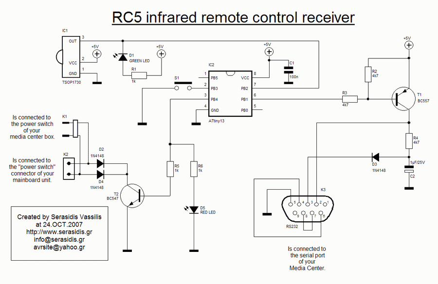
Some time ago, a media center box was created to replace a DVD player, satellite receiver, VCR, and PlayStation 2 with a single device. A Core 2 Duo processor system successfully replaced all these electronic devices. However, a remote...

A small ultrasonic cleaning device currently operates with one 50W transducer. There are plans to construct another device using two 20W transducers, and the best configuration for wiring them—either in series or in parallel—is being considered. The circuit designs...

This design circuit is for an electrostatic transducer used in ultrasonic measurement applications. It employs the LM1812 ultrasonic transceiver. The transducer (X1) and the LM1812 work together to transmit a burst of oscillations. The return echo is detected by...
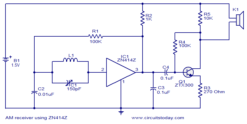
The circuit diagram of the single-chip AM radio is designed around the IC ZN414Z, which consists of ten transistors tuned for radio frequency reception. The single-chip AM radio circuit utilizing the ZN414Z integrated circuit (IC) is a compact and efficient...
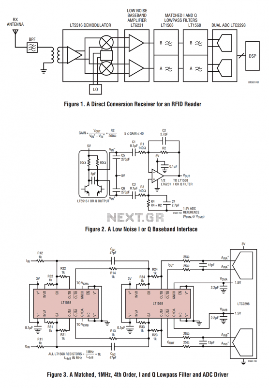
Figure 1 shows the block diagram of a direct conversion RF receiver—the receiver demodulates an RF carrier directly into a baseband signal without an intermediate frequency down-conversion (a zero IF receiver). The antenna, shared by both the transmitter and...
This web page is a memorial to Mike Caughran, KL7R, who passed away unexpectedly in January 2007. Mike was an enthusiastic experimenter, well-regarded in the homebrew radio electronics community. He is best known as the co-creator and collaborator with...