
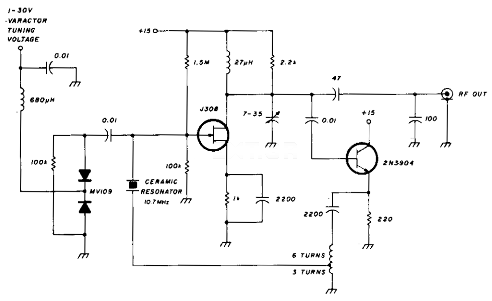
Varactor-Tuned Preselector

Varactor diodes, also known as varicap diodes, are semiconductor devices that exploit the voltage-dependent capacitance characteristics of a reverse-biased p-n junction. In applications such as AM broadcasting, varactor diodes serve as a modern alternative to traditional tuning capacitors, such as the 365-pF capacitors typically used in radio frequency (RF) circuits. The integration of varactor diodes in RF stages allows for a significant reduction in both size and weight of the tuning elements, which is particularly advantageous in compact radio designs.
In the context of a tuned RF stage, the varactor diode operates by varying its capacitance in response to changes in the applied reverse voltage. This property enables precise tuning across the desired frequency range, enhancing the performance of AM broadcast receivers. The use of varactor diodes not only simplifies the circuit design by eliminating the need for bulky capacitors but also improves the overall efficiency of the RF stage.
The selectivity of the RF stage remains adequate for use as a tuned radio frequency (TRF) receiver, especially when a detector circuit is connected to terminal J2. This configuration allows for effective demodulation of the AM signal, ensuring that the receiver can distinguish between closely spaced frequencies. The incorporation of varactor diodes thus represents a significant advancement in RF circuit design, providing a compact solution without compromising performance. Varactor diodes replace the conventional 365-pF tuning capacitors, which reduces size and weight when used as a turned RF stage for AM broadcast applications. Selectivity is good enough for use as a TRF receiver if a detector is connected to J2.
Related Circuits
Once again, this is a project designed by David Sayles. The input can be from a longwire or a loop antenna. The unit covers MW and Sw to 30MHz. This project involves a versatile antenna interface designed to accommodate...
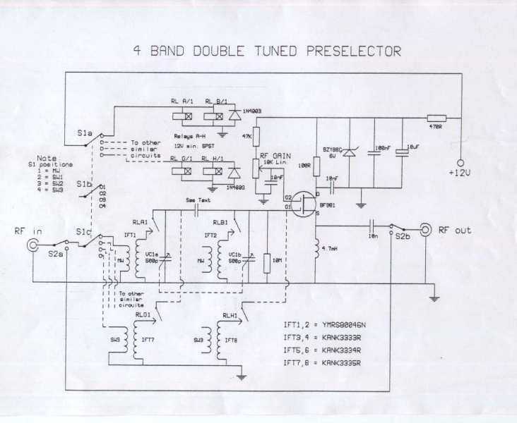
This is a preselector circuit designed for shortwave (SW) receivers, specifically a do-it-yourself (DIY) high-frequency preselector. The circuit employs a modern low-capacitance MOSFET with two gates, which generates a negative inverse reaction through an uncoupled source resistor. When applied...
The FET input amplifier utilizes fixed bias with source feedback, resulting in a very high input impedance and low capacitance. An emitter follower is driven by the FET amplifier, which, despite its low output impedance, feeds a transformer with...
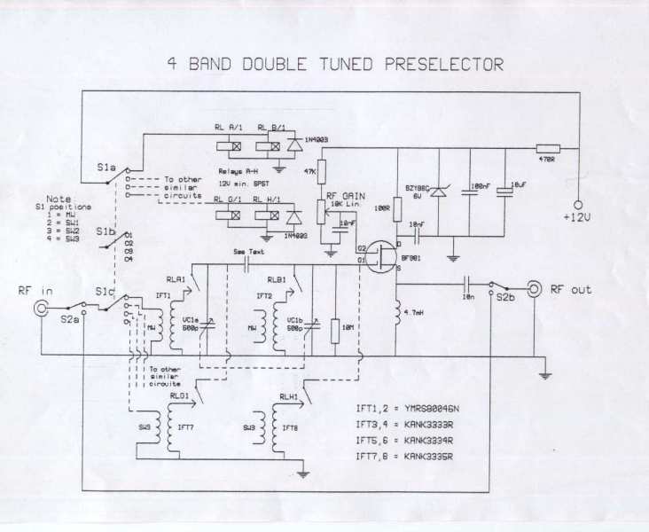
The circuit requires an RF input, which can be sourced from either a long wire or a loop antenna. The preamplifier operates within a frequency range from 550 kHz (Medium Wave) up to 30 MHz in the shortwave band....