
Modulation monitor

The broad-tuned receiver operates by utilizing a loosely coupled wire antenna, which is strategically positioned in proximity to the transmitting antenna. This setup allows the receiver to capture a wide range of radio frequency (RF) signals effectively. The loosely coupled wire acts as an inductive element, enabling the receiver to demodulate various RF signals without the need for precise tuning to a specific frequency.
In a typical configuration, the broad-tuned receiver includes components such as an RF amplifier, a demodulator, and audio output circuitry. The RF amplifier enhances the weak RF signals received by the wire antenna, ensuring that they are strong enough for subsequent processing. The demodulator then extracts the original information signal from the modulated RF carrier wave, converting it into a baseband audio signal or another form suitable for further use.
The design of the receiver may incorporate various filtering techniques to minimize noise and interference, thus improving the clarity of the demodulated signal. Additionally, the output stage may include audio amplification to drive speakers or headphones, allowing for audible reproduction of the received signals.
Overall, the broad-tuned receiver is an efficient solution for applications requiring the reception of diverse RF signals in environments where precise frequency tuning is not feasible. It is particularly useful in scenarios such as amateur radio, emergency communication systems, and educational demonstrations in the field of electronics.Broad-tuned receiver demodulates the RF signal picked up by a ioosely coupled wire placed near the transmitting antenna.
Related Circuits
Many electronics hobbyists have encountered the situation where a project is being completed late at night and the mains supply fails. The cause of the failure, whether due to the electricity provider or personal oversight, is not significant. In...
This circuit functions as a missing pulse detector, utilized in the General Purpose Controller Board with Basic Stamp 1. It monitors an input pulse train, and when a pulse is missed, the output of the 555 timer switches to...
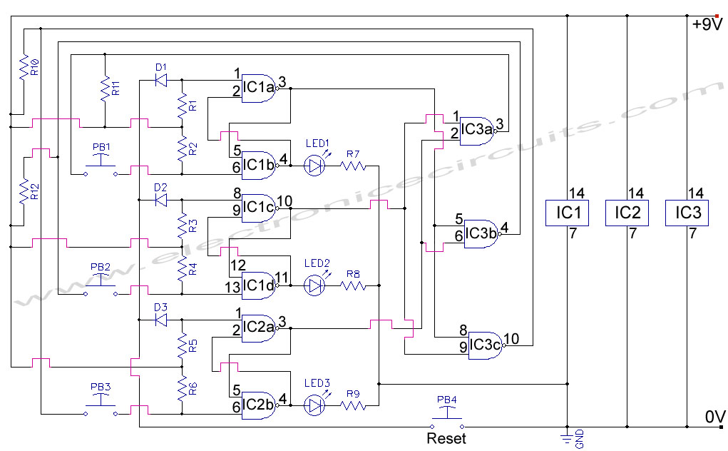
First Response Monitor, Input Selector, Game Circuit. This circuit is utilized for first response applications as it aids in monitoring various responses in games. The First Response Monitor circuit is designed to facilitate real-time monitoring and selection of input signals...

This simple low voltage tester circuit can be used to monitor batteries and other voltage sources for issues, utilizing an LED display and alarm sound. The low voltage tester circuit is designed to provide a reliable method for monitoring the...
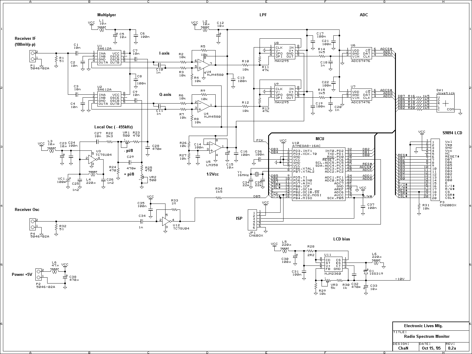
This is an experimental work to monitor a spectrum pattern of radio band, and is a continuous project from Audio Spectrum Monitor. To analyze the spectrum of an input signal, I chose an Atmel's AVR microcontroller used in Audio...
The objective of this project was to monitor power consumption in a residential setting. In addition to tracking total usage, the goal was to separately monitor and compare the usage of major appliances, such as the water heater, heat...