
VOICE LEVEL METER

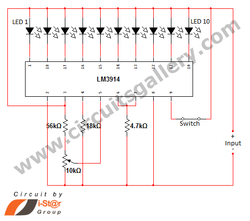
The LM3915 IC is designed for visual representation of analog signals through an LED bar graph or dot display. It is particularly useful in audio applications to create a visual indication of signal levels. The device can drive up to 10 LEDs in a linear or logarithmic scale, depending on the configuration.
To implement this circuit, the audio signal is first amplified using a basic audio amplifier circuit. This amplifier boosts the audio signal to a suitable level for processing. The output from the audio amplifier is then fed into a detector circuit, which typically consists of a rectifier and a smoothing capacitor. This circuit converts the AC audio signal into a DC voltage that corresponds to the amplitude of the audio signal.
The DC voltage output from the detector circuit is connected to the input of the LM3915. The LM3915 interprets this voltage and drives the appropriate number of LEDs based on the input level. In a typical configuration, the IC can be set to operate in either bar graph mode, where all LEDs light up progressively, or dot mode, where only the highest LED lights up.
Additional components may include resistors for setting the reference voltage and capacitors for filtering noise in the power supply. Proper power supply decoupling is essential to ensure stable operation of the LM3915, minimizing fluctuations that could affect the LED output.
Overall, this circuit provides an effective and visually engaging way to monitor audio signal levels, making it suitable for applications in audio equipment, mixers, and other sound engineering tools.Using an LM3915 VU meter LED bar graph driver?10 LEDs are driven?A simple audio amplifierdrives a detector circuit?which provides dc drive for the LM3915.. 🔗 External reference
Related Circuits
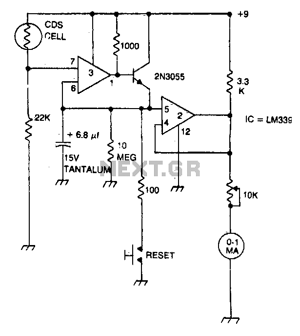
A strobe light meter captures the peak flash intensity and retains it long enough to provide a reading. The reset button must be pressed prior to each measurement. The strobe light meter operates by detecting the peak intensity of light...
An analog meter typically does not exhibit high impedance due to the absence of a buffer circuit within its design. By incorporating active buffering, the input impedance of this circuit can be significantly enhanced. The integration of an active buffer...
In various situations, it is necessary to indicate the amount of battery charge using methods such as LED dot displays or LED bar displays. This circuit utilizes the LM3914 integrated circuit to serve as a battery charge indicator with...
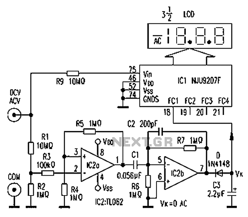
The circuit depicted in the figure illustrates an automatic AC/DC converter for a digital multimeter. Typically, standard digital multimeters require manual intervention to switch between AC and DC measurements. The new DT860D digital multimeter utilizes the NJU9207F automatic range...
40-meter Direct Conversion Receiver. Using the circuit of a 40-meter band direct-conversion receiver described here, one can listen to amateur radio QSO signals in both CW and SSB modes. The 40-meter direct conversion receiver is designed to facilitate the reception...
Pulses are received by the timer from the distributor points. When the timer output is high, Meter M receives a calibrated current through R6. The meter does not... The circuit described involves a timer that receives pulse signals from distributor...