
voltage frequency synthesizer PLL

The µA2240 integrated circuit is designed for applications requiring precise timing and frequency generation. It comprises four essential components: a time-base oscillator (TBO), an eight-bit counter, a control flip-flop, and a voltage regulator, each contributing to the overall functionality of the device.
The time-base oscillator generates a clock signal at a frequency determined by the external resistor (R1) and capacitor (C1) values, with a specific time constant calculated as 1R1C1 = 2 kHz. This oscillator's open-collector output is connected to the input of the eight-bit counter, which counts the pulses generated by the TBO. A 20 k ohm pull-up resistor is employed to ensure proper voltage levels at the counter input, facilitating reliable operation.
Upon power-up, the circuit is initialized by a positive trigger pulse detected across capacitor C2. This pulse activates the TBO, initiating the oscillation process and setting all outputs of the counter to a low state. The µA2240 operates in an astable mode, meaning that once triggered, it will continue to run independently until an external reset signal is received. This behavior allows for continuous frequency generation without the need for constant triggering.
The eight-bit counter can synthesize up to 255 distinct frequencies by selectively connecting various counter outputs. This versatility in frequency generation makes the µA2240 suitable for a wide range of applications, including signal generation, timing applications, and digital clock circuits. The integrated voltage regulator ensures stable operation across varying supply voltages, contributing to the device's reliability and performance in electronic designs.The µA2240 consists of four basic circuit elements: (1) a time-base oscillator, (2) an eight-bit counter, (3) a control flip-flop, and (4) a voltage regulator. The basic frequency of the time-base oscillator (TBO) is set by the external time constant determined by the values of R1 and Cl (1R1C1 = 2 kHz).
The open-collector output of the TBO is connected to the regulator output via a 20 k ohm pull-up resistor, and drives the input to the eight-bit counter. At power-up, a positive trigger pulse is detected across C2 which starts the TBO and sets all counter outputs to a low state.
Once the µ2240 is initially triggered, any further trigger inputs are ignored until it is reset. In this astable operation, the µ2240 will free-run from the time it is triggered until it receives an external reset signal. Up to 255 discrete frequencies can be synthesized by connecting different counter outputs.
Related Circuits
A frequency-selective frequency multiplier can be constructed using a Phase-Locked Loop (PLL) system by incorporating a frequency divider within the feedback loop between the phase detector input and the Voltage-Controlled Oscillator (VCO) output. The accompanying schematic diagram illustrates a...
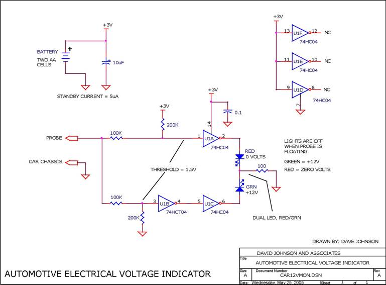
When troubleshooting the 12V electrical system of an automobile, it is beneficial to have a simple voltage indicator tool instead of a voltmeter. This electronic circuit is powered by two AA batteries or two N cells, providing sufficient energy...
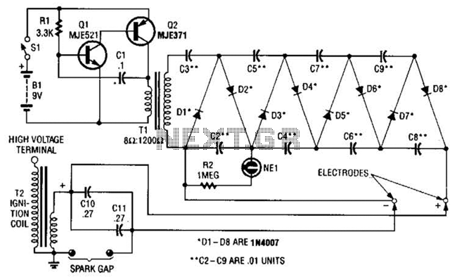
This circuit employs a transistor oscillator and a voltage multiplier to charge capacitors CIO and CI1 to a high voltage. When the spark gap breaks down, T2 generates a high-voltage pulse through the discharge of capacitors CIO and CI1...
This circuit is connected to a motorcycle and is integrated into a circuit that is powered only when the key is in the "ON" position. If the motorcycle is turned off using the kill switch while the key remains...
This is a circuit for a Voltage-to-Pulse Duration Converter. The circuit is designed to convert voltage into pulse duration by integrating a timer IC and an operational amplifier (OP Amp). The Voltage-to-Pulse Duration Converter circuit utilizes a timer IC, typically...

This circuit is designed for higher input or output voltages in an L200 voltage regulator. It addresses issues that arise when input or output voltages exceed the regulator's specifications. The circuit incorporates external components, including a transistor that absorbs...