
Wideband RF Field Strength Meter

A field strength meter serves as an essential tool for RF engineers and technicians, facilitating the testing and troubleshooting of RF circuits. The basic construction of a field strength meter involves an LC circuit, which consists of an inductor (L) and a capacitor (C) that are tuned to resonate at a specific frequency. This resonant frequency allows the meter to respond effectively to RF signals within its operational range.
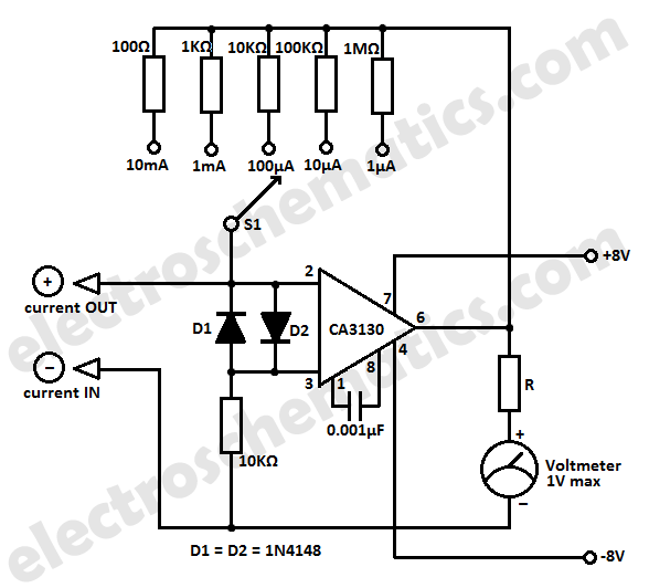
The use of a germanium diode in this configuration is critical, as it acts as a rectifier, converting the RF signal into a direct current (DC) signal that can be measured. The high-sensitivity current meter, which replaces the earpiece of a traditional crystal radio, provides a visual representation of the field strength by indicating the strength of the detected RF signal.
While the simple LC circuit design is adequate for many applications, its limited frequency range poses challenges for more advanced RF measurements. To address this, additional components such as variable capacitors or inductors can be introduced to allow for tuning across a broader frequency spectrum. However, this increases the complexity of the design and may require more sophisticated calibration techniques.
In practical applications, field strength meters can be employed for various tasks, including antenna alignment, signal strength assessment, and interference detection. Understanding the limitations and capabilities of the field strength meter is crucial for effective use in RF applications. Proper calibration and tuning are essential for accurate measurements, and users must be familiar with the characteristics of the specific RF environment in which the meter is deployed.Field strength meter is extremely useful when working with RF devices. It can be used to quickly diagnose whether a transmitter circuit is working, and can be used to detect RF signals in the environment. The simplest field strength meter could be built with a tuned LC circuit and a germanium diode, just like the way of a building a crystal radio except replacing the ear piece with a high sensitivity current meter.
While this approach fits the needs of most simple applications, it has a pretty narrow frequency range (~100 MHz) and requires tuning the LC circuit to the correct frequency before measurements can be made and the design can become complicated if wider frequency range tuning is desired 🔗 External reference
Related Circuits

This digital thermometer circuit diagram utilizes a common 1N4148 diode as the temperature sensor. The diode's temperature coefficient of -2 mV/°C is leveraged to create an accurate electronic thermometer. A digital multimeter is employed to display the measured temperature,...
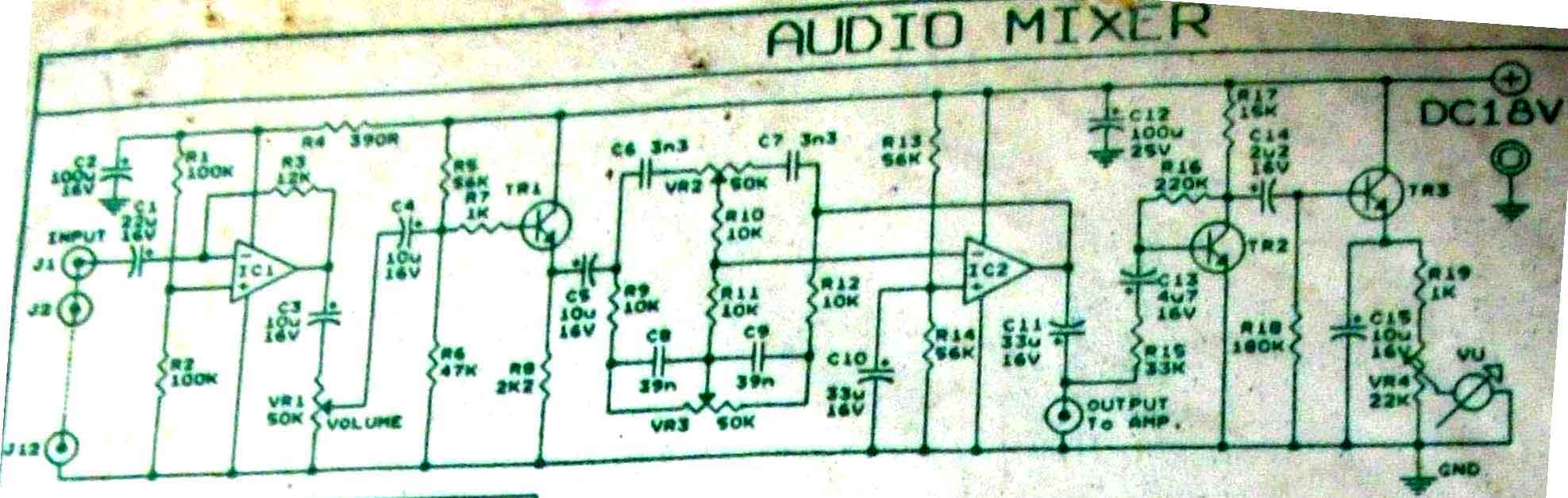
This is audio mixer circuit. The circuit is for one channel input, if you need, for example 5 channel mixer, then you need to build 5 similar circuits. The audio mixer circuit described is designed to handle a single channel...
This LC meter circuit is capable of measuring inductors and capacitors. When either Lx or Cx is connected to the circuit, the oscillator frequency decreases, and this reduction is measured by a frequency-voltage converter constructed with transistors T3 and...

A simple technique for measuring frequencies across a wide range with acceptable accuracy limits using a PC is presented. This method follows the basic principle of measuring low frequencies, where the period of a complete wave is measured and...
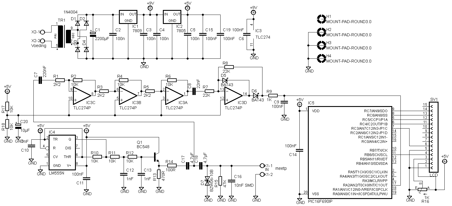
Two versions are provided. The first version is based on the original schematics, with the modification of replacing SMD capacitors with standard through-hole capacitors. The second version features some modifications, including the removal of the transformer and the addition...
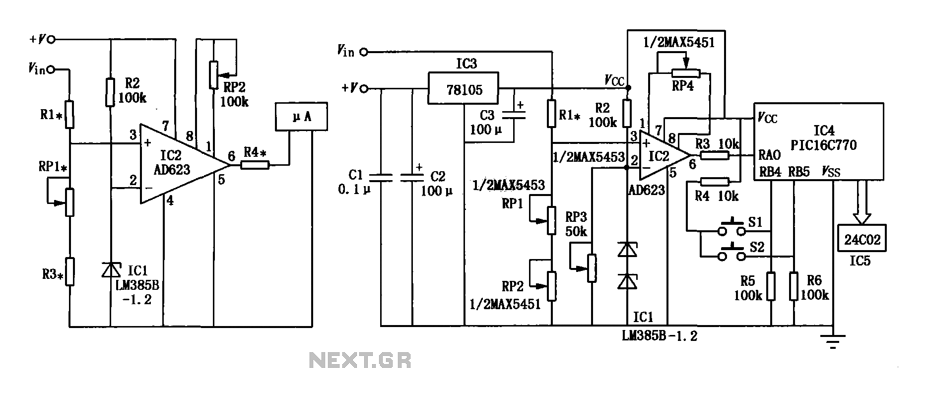
The range precision voltmeter electrical schematic is depicted in Figure (a) below. It features an amplifier circuit and several high-precision components that significantly enhance the performance range of the voltmeter. The inverting input of the instrumentation amplifier AD623 (IC2)...