
Wien bridge oscillator

The described circuit features a frequency trimming component that plays a crucial role in maintaining stability while allowing for fine-tuning of frequency characteristics. The quadrature arrangement with the bridge voltage V0 ensures that modifications to the trimming component have a negligible impact on the overall attenuation, which is essential in applications where precise signal integrity is required. This design choice effectively circumvents the complexity and potential performance issues associated with dual-gang components, which are typically used for simultaneous adjustments in frequency and amplitude.
The implementation of a high-gain amplifier is vital for achieving the desired loop gain, which is set just at the threshold of oscillation. This careful calibration allows for optimal performance without introducing instability into the circuit. Metal film feedback resistors are selected for their excellent thermal stability and low noise characteristics, which contribute to the overall reliability and accuracy of the circuit.
By removing the need for an automatic gain control mechanism, such as a thermistor, the design simplifies the circuit architecture while enhancing its performance. This is particularly beneficial in applications where temperature variations might otherwise affect gain stability. The limited frequency variation range is a deliberate design choice, ensuring that the circuit remains focused on a specific operational bandwidth, which can be critical in precision applications such as communication systems or sensor interfaces.
Overall, this circuit design exemplifies a balance between simplicity and functionality, providing a robust solution for frequency adjustment while minimizing the potential for signal degradation.In the circuit the frequency trimming component is arranged so that the voltage across it is in quadrature with the voltage V0 from the bridge so that as it is adjusted the attenuation of the bridge only changes a little, avoiding the need for a two gang component. The range of variation of frequency is very limited. By using a high gain amplifier and metal film feedback resistors the loop gain can be set so that the unit just oscillates and the use of an automatic gain setting component, a thermistor for example, is eliminated.
Related Circuits
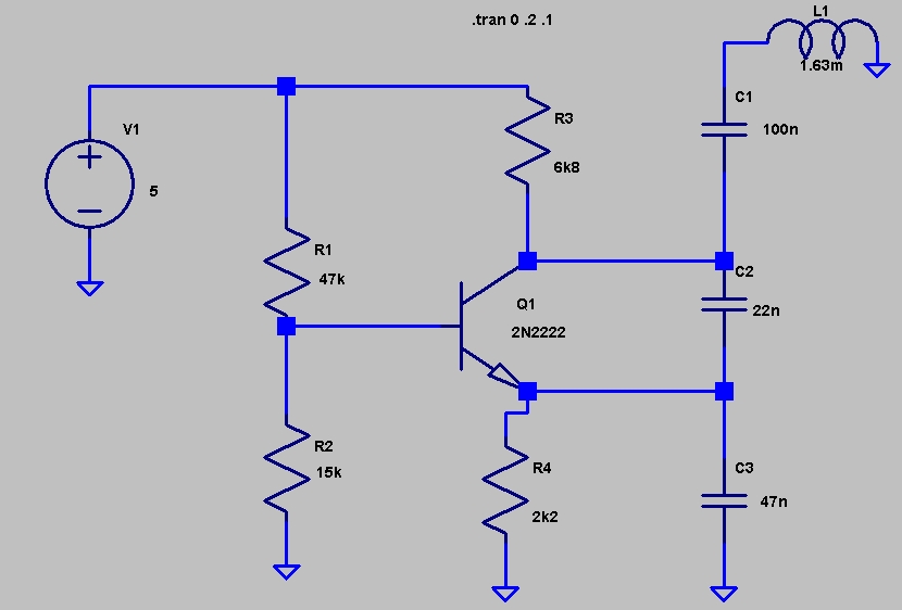
This circuit was featured in the "design ideas" section of EDN's March 5, 2007 issue. It is a relatively simple circuit that allows investigation into how the inductance of a toroid (or any core) is affected by saturation, which...
A NE555 integrated circuit (IC) is utilized for the design of a variable low-frequency oscillator, and a schematic is provided. The NE555 timer IC is a versatile and widely used device in various electronic applications, particularly in generating precise timing...
In this version of the oscillator, Rb is a small incandescent lamp. Typically, R1 = R2 = R and C1 = C2 = C. During normal operation, Rb self-heats to the point where its resistance is Rf/2. A Wien...
An oscillator circuit is an electronic circuit that produces a periodic signal. The term quadrature refers to a fourth (1/4) phase shift of a full wave cycle (1/4 of... An oscillator circuit is a fundamental component in various electronic systems,...
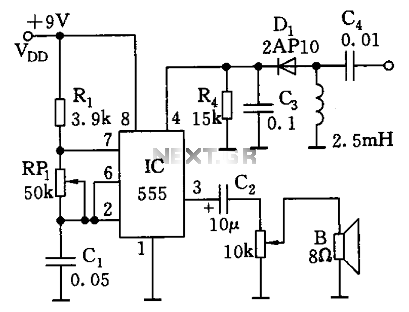
The circuit features a 555 timer along with resistors R1, RP1, and capacitor C1, functioning as a controllable audio oscillator. The frequency of the oscillator is determined by the formula f = 1.44 / ((R1 + 2 * RP1)...
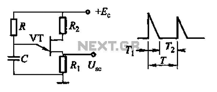
Common non-sinusoidal oscillator circuit, waveform and frequency formula - pulse wave oscillator - blocking oscillator transformer The common non-sinusoidal oscillator circuit is designed to generate pulse waveforms, which are characterized by their square or rectangular shape. These oscillators are...