
Simple and practical electric vehicle anti-theft alarm circuit diagram
The electric vehicle anti-theft alarm system is designed with several critical components to ensure reliability and effectiveness. The circuit begins with the alarm transmitter, where the relay K acts as a control mechanism to manage power to the alarm system. The thyristor VS plays a crucial role in activating the relay, allowing for a quick response when unauthorized access is detected.
The radio frequency oscillation circuit, formed by components surrounding IC1, generates a unique alarm signal that is transmitted when the system is activated. The standby mode is maintained by the S1 switch, which keeps the alarm inactive while the vehicle is secured. The connection status of SB1 is vital; when the front door is unlocked, it triggers the system into an active state, allowing the relay to engage and power the transmitter.
The receiver circuit, including the TDA7010 amplifier, is responsible for detecting the transmitted alarm signal. The amplification stages provided by IC2, IC3, and IC4 ensure that the alarm signal is sufficiently strong to be recognized, even at a distance. The integration of TWH8778 and TWH68 enhances the overall performance of the receiver circuit, ensuring robust communication between the transmitter and receiver.
To enhance the system's reliability, it is advisable to implement a frequency stabilization mechanism for the TDA7010, as fluctuations in frequency can affect the performance of the alarm system. Testing with printed circuit boards (PCBs) and surface-mount device (SMD) components will provide a more stable and reliable system.
This alarm system not only serves as a deterrent against theft but also ensures that any unauthorized attempt to access or move the vehicle results in an immediate response, thereby protecting the owner's investment and enhancing the security of electric vehicles.As environmental awareness increases, the electric car has been poured into our family, become an indispensable part of peoples transport. How to prevent the electric car theft is a problem of great concern to the owners, to this end, there have been all kinds of electric vehicle anti-theft lock. However, the electric car theft phenomenon still emerging, more advanced electric vehicle anti-theft locks in a short time is difficult to destroy, put the thieves stole the electric car onto other vehicles, so then advanced anti-theft lock also appears powerless.
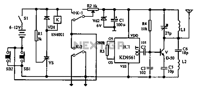
In view of this, we introduce an electric vehicle anti-theft alarm system circuit diagram. Alarm transmitter portion of the transmitter circuit is controlled by the power relay K and thyristor VS used. Offbeat signal circuit IC1 composition. V and its peripheral components transistor radio frequency oscillation circuit, transmit an alarm signal.
In the wait state, the switch S1 is turned on, and SB1 disconnect (ie front lock is locked), K is in releasing state to the alarm transmitter does not work. When the front door was unlocked (ie SB1 ON), VS is triggered conduction, K pull, turn the transmitter power.
After SB1 connected to the normally open points K-2 in its self-locking, only this time off S1 alarm can only end. When K operation, the normally closed contacts Kl off, cut off the engine ignition circuit. Receiver circuit and a switch by the TDA7010 amplifier TWH8778, TWH68 composition. When the alarm signal is received their mutual IC2 feet high by IC3 via IC4 amplified by TWH15 release alarm.
But taking into account the frequency stability, because no frequency stabilization circuit 7010 itself, when the work should make more testing, preferably with PCB and SMD components. According to the above method of operation parked vehicle, the alarm enters the alarm state to be. During the alarm to be, as long as someone no matter what method to open the front lock or move the vehicle, the alarm will trigger an alarm stop, and cut off the engine power of the vehicle can not be started until the owner who came to the ignition key is inserted in the ignition lock oFF position, the alarm can be lifted.
Related Circuits
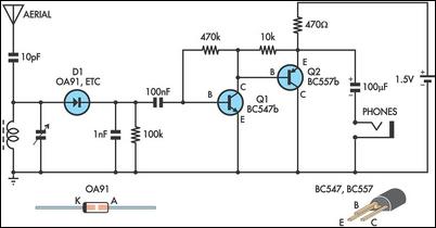
This circuit is essentially an amplified crystal set. The inductor could be a standard AM radio ferrite rod antenna while the tuning capacitor is a variable one. The described circuit operates as an amplified crystal radio receiver, which utilizes a...
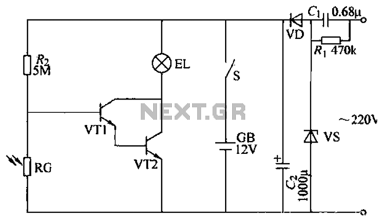
The power supply circuit features a step-down capacitor (C1), bleeder resistors (R), a Zener diode (VS), a full diode (VD), and a filter capacitor (G), along with switches and batteries (GB, SC). The light control circuit is composed of...

This circuit is a laser alarm system similar to those depicted in various movies. It employs a laser pointer beam to secure valuables and property. When the beam is interrupted by a person, animal, or object, the resistance of...
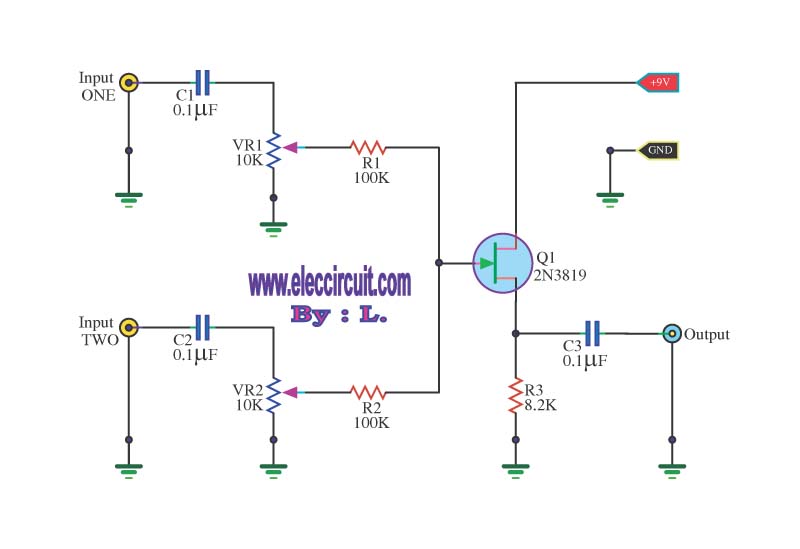
This circuit is a simple mixer circuit that can mix two signal channels into one output channel. It utilizes a codec circuit to convert stereo audio into mono audio. The circuit can also increase the number of channels by...
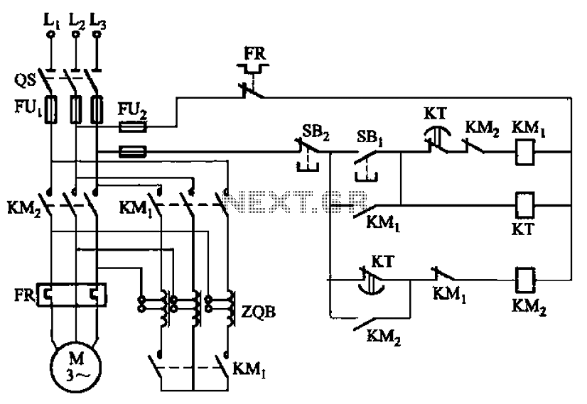
The circuit depicted in Figure 3-49 illustrates an autotransformer that is controlled by a time relay (KT). The delay time set by the KT relay corresponds to the motor's startup duration. The circuit utilizes an autotransformer, which is a type...
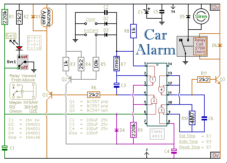
This circuit includes automatic exit and entry delays, an optional instant alarm zone, an optional intermittent siren output, and an automatic reset feature. By incorporating external relays, it is possible to immobilize the vehicle and activate the lights. For...
Warning: include(partials/cookie-banner.php): Failed to open stream: Permission denied in /var/www/html/nextgr/view-circuit.php on line 713
Warning: include(): Failed opening 'partials/cookie-banner.php' for inclusion (include_path='.:/usr/share/php') in /var/www/html/nextgr/view-circuit.php on line 713