
1 Khz Inductance Meter ATTINY861
More: Looking around on the web a little more, found the user's manual for an M3 Electgronix Digital LCRZ Meter kit, which, aside from spelling out the meter's impressive capabilities, also explained a few short paragraphs explained how the meter worked. That was enough to convince me to give this technique a try. By the way, if case you are starting to get the idea that this project is a quick and dirty knock-off of the M3 design, its not. The M3 kit has much more range, measures lot more than just inductance, and seems to be quite a bit more accurate.
My project is just an exploration of circuit and firmware techniques, mostly to see what it would take to get such an instrument operating. I think that if you have the time to build the kit, the M3 kit is an excellent way to get a full function LCRZ measurement capability that rivals that of some of the most expensive factory built instruments, but at fraction of the cost. You might want to have a look at the M3 Electgronix webiste, and in particular at the web page for their meter kit. You can even download the manual for their kit on the page at this link: http://www.m3electronix.com/lcr.html.
The result of this investigation is some circuit concepts, some firmware techniques, and some learning. Notably, the internal reference impedances are switched on and off without the use of electromechanical relays or switches, and a comparatively low parts count version can be made with some sacrifice in measurement linearity. The ATTINY861 that I chose to use in this investigation seemed to have way more program space that I thought I would need - 8 k Bytes, in all, but as the design progressed, the space filled up rapidly. Soon, I was at the point of scrimping to save memory. I think an experienced embedded C programmer would be able to find plenty of places in my code where space can be saved, but this was all I could cram into that chip.
My meter has two ranges: From about 0.6 to 33 Ohms and a higher, overlapping range from about 30 Ohms to about 330 Ohms. Having only two ranges, made it easy to switch ranges automatically.
In designing the meter, I assumed the most useful model to me: a pure inductor in series with a pure resistance. I ignore capacitance all together. The meter calculates and displays the impedance of the inductor under test, the angle of the voltage across the inductor with respect to the driving current, and displays the actual inductance and resistance. The resistance display can be switched between resistance and Q, where Q is defined as the impedance divided by the resistance.
Taking a hint from the M3 Electgronix manual, the instrument is first calibrated with the use of a precision resistor, which is measured and compared against an internal reference, thus calibrating the internal reference. The internal reference is then used for future calibration. Calibration parameters, for both the original calibration and subsequent calibrations using the internal reference, are stored in the EEPROM on the ATTIN618 micro controller.
As a result of running out of program memory, I was not able to get the data display to work to my liking. Below 100 uH, the decimal point disappears, and can be a problem. A 90 uH inductor, for example, looks like 9 mH on the display.
This is a good time to mention patents. Don't assume that anything you read on this web site is not covered by somebody's patent(s) somewhere in the world. I have seen methods similar to this one mentioned in issues U.S. utility patents, and given the breadth of technologies and techniques covered in this project, I think the only safe assumption is that commercial use of this circuit would infringe on some patent. As mentioned previously, the intent of this project is to learn, not to devise a design for a product.
The project involves the design and implementation of a digital inductance meter operating at a test frequency of 1 kHz. The selection of this frequency is critical, as it minimizes the effects of the test current on the measurement accuracy, particularly for magnetic cores and soft ferrites, which exhibit changes in permeability based on the current flowing through the inductor. A peak-to-peak test current of 1.0 mA is chosen to ensure minimal interference.
The circuit design incorporates an ATTINY861 microcontroller, which provides sufficient program memory (8 k Bytes) for the intended functionalities. The device is capable of measuring inductance down to 100 µH and displays not only the inductance but also the impedance and phase angle of the inductor under test. The measurement process is enhanced by the use of a precision resistor for calibration, ensuring accurate reference values are established and stored in the microcontroller's EEPROM.
The meter features two resistance measurement ranges, allowing for automatic switching between a lower range (0.6 to 33 Ohms) and a higher range (30 to 330 Ohms). This facilitates a straightforward user experience while maintaining accuracy across a broad spectrum of inductance values. The design assumes a simplified model of a pure inductor in series with a pure resistance, intentionally ignoring capacitance for the sake of measurement clarity.
In terms of display functionality, there are limitations due to memory constraints, particularly in the representation of values below 100 µH, which can lead to confusion in readings. The design's emphasis on low component count and innovative switching techniques, without electromechanical components, reflects a focus on efficiency and reliability in circuit design. The project serves as a learning platform for exploring circuit and firmware techniques rather than a commercial product, with awareness of potential patent implications surrounding the methodologies employed.1 kHz is a commonly used test frequency, and I resolved to see if I could make an inductance meter that uses a 1 kHz test signal at a low level. I also wanted to use a low level test signal so that the test current would have a minimal effect on the measurement.
Magnetic cores, and soft ferrites in particular, change in permeability as a function of the current through the winding. I chose 1.0 milliamps peak-to-peak as a test current. Given that I wanted to be able to measure inductance down to 100 uH, my attention turned to the problem of how to accurately measure the amplitude and the phase of as little as 63 millivolts across a 100 uH inductor.
Looking around on the web a little more, found the user's manual for an M3 Electgronix Digital LCRZ Meter kit, which, aside from spelling out the meter's impressive capabilities, also explained a few short paragraphs explained how the meter worked. That was enough to convince me to give this technique a try. By the way, if case you are starting to get the idea that this project is a quick and dirty knock-off of the M3 design, its not.
The M3 kit has much more range, measures lot more than just inductance, and seems to be quite a bit more accurate. My project is just an exploration of circuit and firmware techniques, mostly to see what it would take to get such an instrument operating.
I think that if you have the time to build the kit, the M3 kit is an excellent way to get a full function LCRZ measurement capability that rivals that of some of the most expensive factory built instruments, but at fraction of the cost. You might want to have a look at the M3 Electgronix webiste, and in particular at the web page for their meter kit.
You can even download the manual for their kit on the page at this link: http://www.m3electronix.com/lcr.html. The result of this investigation is some circuit concepts, some firmware techniques, and some learning.
Notably, the internal reference impedances are switched on and off without the use of electromechanical relays or switches, and a comparatively low parts count version can be made with some sacrifice in measurement linearity. The ATTINY861 that I chose to use in this investigation seemed to have way more program space that I thought I would need - 8 k Bytes, in all, but as the design progressed, the space filled up rapidly.
Soon, I was at the point of scrimping to save memory. I think an experienced embedded C programmer would be able to find plenty of places in my code where space can be saved, but this was all I could cram into that chip. My meter has two ranges: From about 0.6 to 33 Ohms and a higher, overlapping range from about 30 Ohms to about 330 Ohms.
Having only two ranges, made it easy to switch ranges automatically. In designing the meter, I assumed the most useful model to me: a pure inductor in series with a pure resistance. I ignore capacitance all together. The meter calculates and displays the impedance of the inductor under test, the angle of the voltage across the inductor with respect to the driving current, and displays the actual inductance and resistance.
The resistance display can be switched between resistance and Q, where Q is defined as the impedance divided by the resistance. Taking a hint from the M3 Electgronix manual, the instrument is first calibrated with the use of a precision resistor, which is measured and compared against an internal reference, thus calibrating the internal reference.
The internal reference is then used for future calibration. Calibration parameters, for both the original calibration and subsequent calibrations using the internal reference, are stored in the EEPROM on the ATTIN618 micro controller. As a result of running out of program memory, I was not able to get the data display to work to my liking.
Below 100 uH, the decimal point disappears, and can be a problem. A 90 uH inductor, for example, looks like 9 mH on the display. This is a good time to mention patents. Don't assume that anything you read on this web site is not covered by somebody's patent(s) somewhere in the world. I have seen methods similar to this one mentioned in issues U.S. utility patents, and given the breadth of technologies and techniques covered in this project, I think the only safe assumption is that commercial use of this circuit would infringe on some patent.
As mentioned previously, the intent of this project is to learn, not to devise a design for a product. 🔗 External reference
Related Circuits
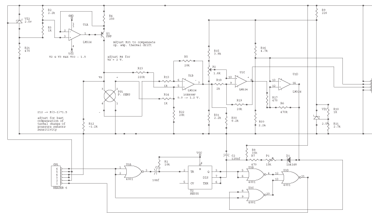
The circuit is powered by the receiver's pack, the current drain is low, especially if compared to drain of servos. U1a VZ2 and Q1 are the current source of the sensor. VZ2 is temperature compensated; use the listed component...
The form of a musical signal never resembles a square wave. The frequency range perceived by an average adult rarely exceeds 17 kHz. Therefore, the appropriateness of testing audio amplifiers with a 100 kHz square wave signal is often...
Using the circuit of 40-metre band direct-conversion receiver described here, one can listen to amateur radio QSO signals in CW as well as in SSB mode in the 40-metre band. The circuit makes use of three n-channel FETs (BFW10)....
Quad comparators, type LM339. A flyback DC converter, a buck converter, and a step-up converter are involved. The design utilizes several comparators and incorporates multiple LEDs. The concept evolved into a VU meter with a desire for a more...
Output transformer core sourced from a flea market, light blue in color, marked as A-438281-2-9H9-3, with an outer diameter of 47 mm, an inner diameter of 24 mm, and a height of 13 mm. No data is available regarding...
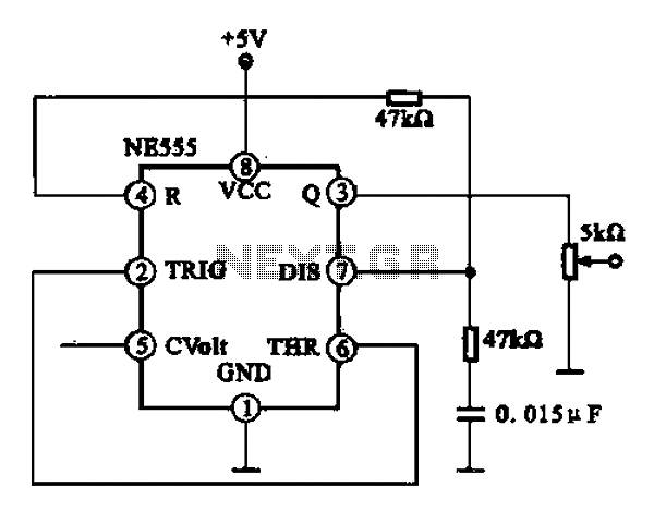
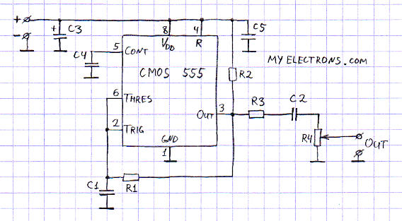
A 1 kHz square wave signal generator is created using a time base circuit with an NE555 timer, combined with a time constant circuit consisting of a 47 kΩ resistor and a 0.15 µF capacitor. The circuit utilizes the...