
1-Ma Current Sink
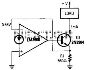
In this circuit configuration, the operational amplifier (op-amp) is utilized to maintain a constant current through a load connected to the collector of transistor Q1. The grounding of the non-inverting terminal establishes a reference point for the op-amp, ensuring that it operates in a linear region. The negative feedback path from the emitter of Q1 to the inverting terminal of the op-amp is crucial for regulating the output voltage and, consequently, the current flowing through the load.
The voltage across resistor R1, which is connected in series with the load, is monitored to provide feedback to the op-amp. Given that the voltage at the inverting terminal is approximately 0.55 V, this indicates that the op-amp is configured to maintain a specific output voltage level. The relationship between the voltage across R1 and the current through it can be described using Ohm's Law, where the current I through R1 can be expressed as I = V/R. In this case, with a fixed voltage of approximately 0.55 V, and assuming R1 is appropriately sized, a constant current of about 1 mA is established.
This configuration is commonly used in applications where a stable current is required for driving loads such as LEDs, sensors, or other electronic components. The stability of the current is a result of the feedback mechanism, which continuously adjusts the output of the op-amp to counteract any variations in load conditions, ensuring reliable operation across different scenarios. The choice of components, including the characteristics of Q1 and R1, plays a significant role in determining the overall performance and efficiency of the circuit. A fixed current flows through any load that is connected between the positive supply and Ql"s collector. The noninverting terminal of the op amp is grounded, and negative feedback flows between the output of the circuit (Ql"s emitter) and the inverting terminal. The voltage across Rl is thus equal to the voltage at the inverting terminal (approximately 0.55 V), so a fixed current of about 1 mA flows through the load, Ql"s emitter, and Rl.
🔗 External reference
Related Circuits
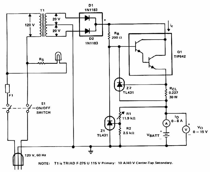
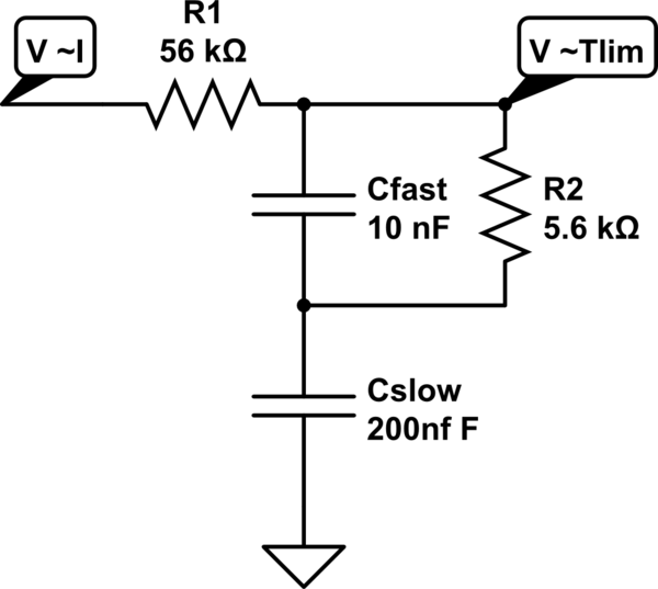
Lead Acid Battery Charger with current limit power supply. Refer to the specified page for an explanation of the related circuit diagram. The lead-acid battery charger with a current limit power supply is designed to safely charge lead-acid batteries while...
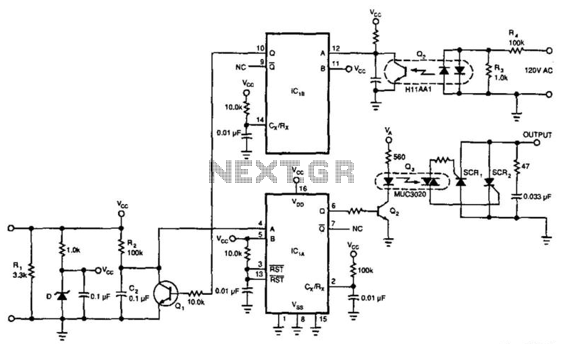
This circuit enables a 4-to-20 mA current loop to control an isolated SCR drive. IC1A and IC1B function as one-shot timers. Q2 detects zero crossings of the 120 Vac line, which triggers one-shot IC1B. IC1A causes Q1 to discharge...
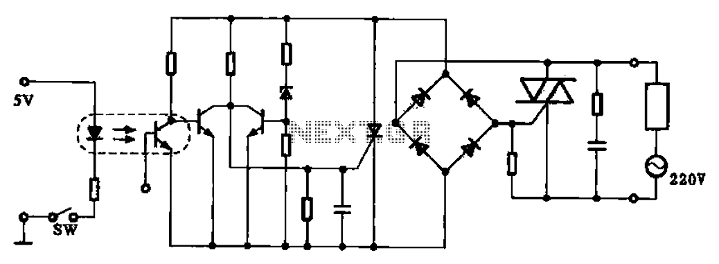
This application example illustrates a photovoltaic control circuit. In this circuit, the Triac functions as a solid-state relay, providing an AC power supply path to the load. It is designed to achieve high current control signals using a small...
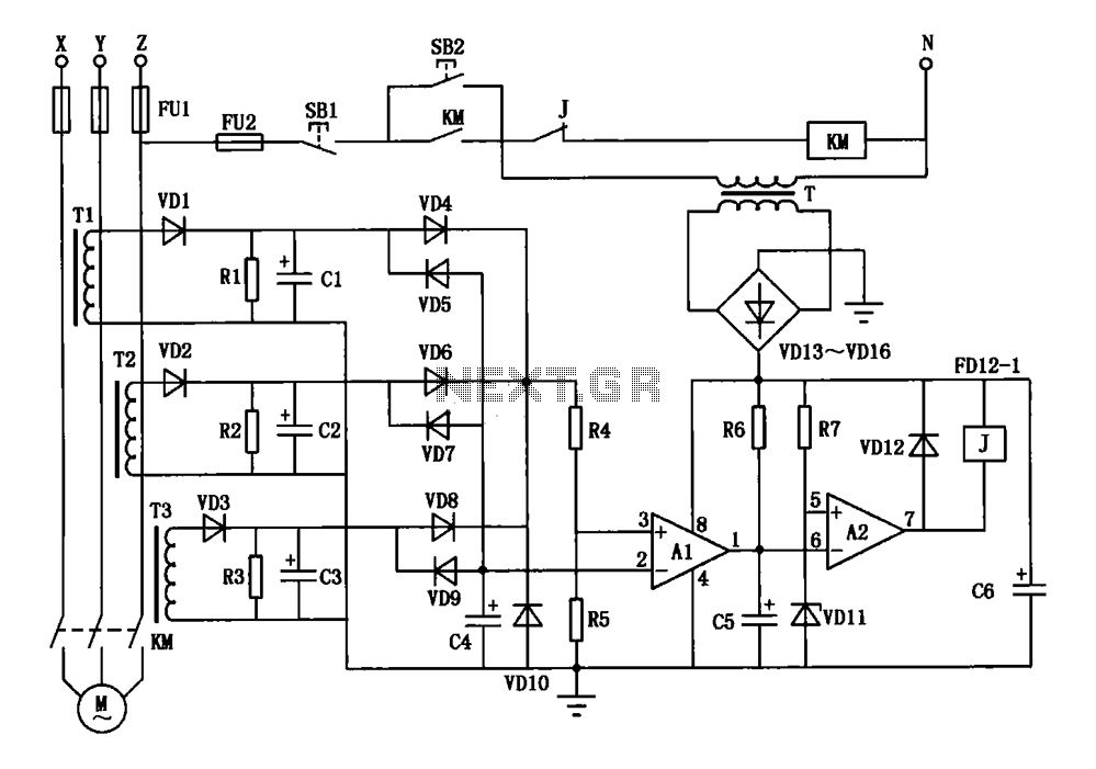
A current three-phase motor phase protection circuit is designed to detect three-phase current using homemade small current transformers T1, T2, and T3. The current signals are collected by rectifiers VD1, VD2, and VD3, while capacitors C1, C2, and C3...
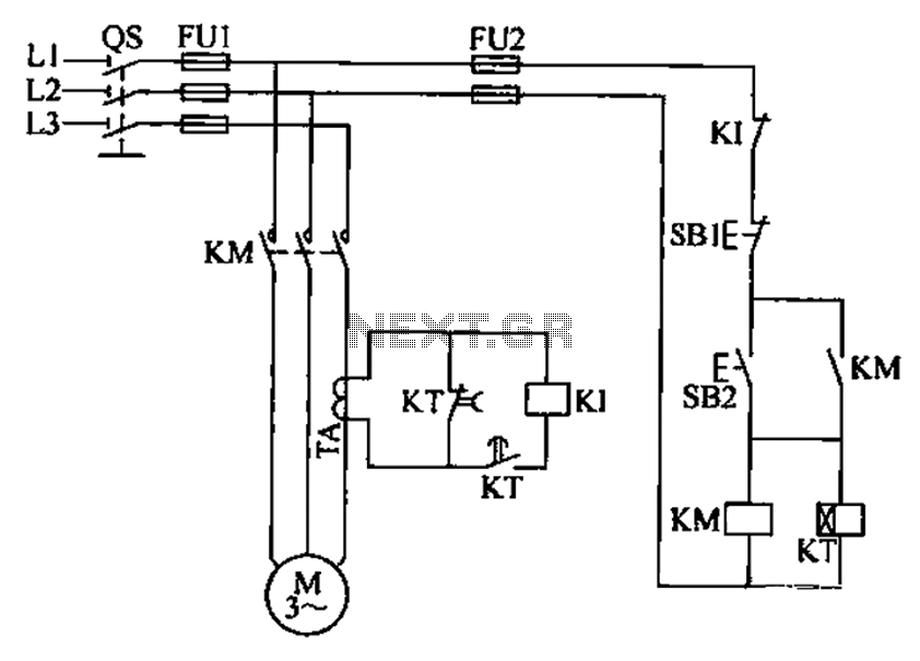
A three-phase electric motor overcurrent protection circuit. This example circuit utilizes a transformer to monitor the current, ensuring that the currents in the three-phase motor do not exceed normal operating levels. When the current exceeds the set threshold, the...
A MOSFET is employed to drive a load that includes a sense resistor in its current path. The voltage across this resistor is utilized to trigger a circuit capable of disconnecting the load in the event of an overcurrent...