
100Hz-1MHz a circuit diagram of the phase meter
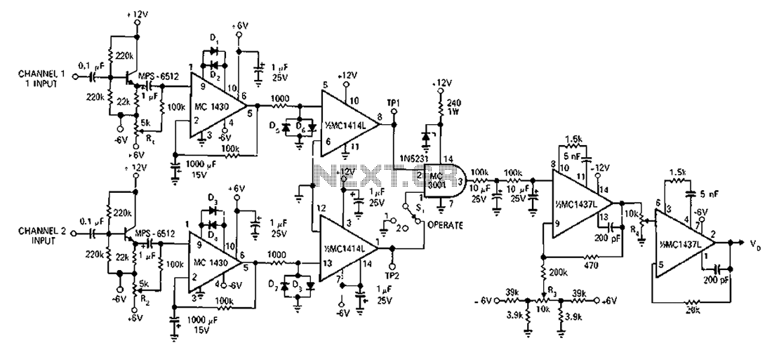
The described circuit is intended for precise frequency analysis and is particularly useful in control systems and signal processing applications. It utilizes two sine wave inputs, which are typically generated by function generators or oscillators. The conversion of these sine waves into a square wave is achieved through a comparator or a Schmitt trigger, which ensures that the output transitions cleanly between high and low states.
The overlap of the input sine waves is crucial for determining the characteristics of the resulting square wave. This overlap is defined in relation to the total cycle of the input waveform, impacting the duty cycle of the output signal. The circuit is designed to maintain an accuracy of greater than 2%, which is essential for reliable Bode plot generation, allowing for the analysis of system frequency response.
The mention of a 180-degree phase difference indicates that the sine waves are out of phase, which can be used to create a specific response in the square wave output. This phase manipulation is critical in applications where phase relationships between signals are important, such as in feedback systems or phase-locked loops.
To implement this circuit effectively, careful selection of components is necessary, including operational amplifiers for signal conditioning, resistors for setting gain and offset, and capacitors for filtering. Additionally, the circuit may require calibration to ensure that the output accurately reflects the desired characteristics of the input waveforms. This setup allows for the effective generation of Bode plots, which are instrumental in assessing the stability and performance of various electronic systems. Circuit in the frequency range, an accuracy greater than 2%, for the production of bode curve. Two sine wave into a square wave, while the amount of overlap compared with the t otal input wave cycle. Direct input phase difference between the wave train reaches 180 .
Related Circuits
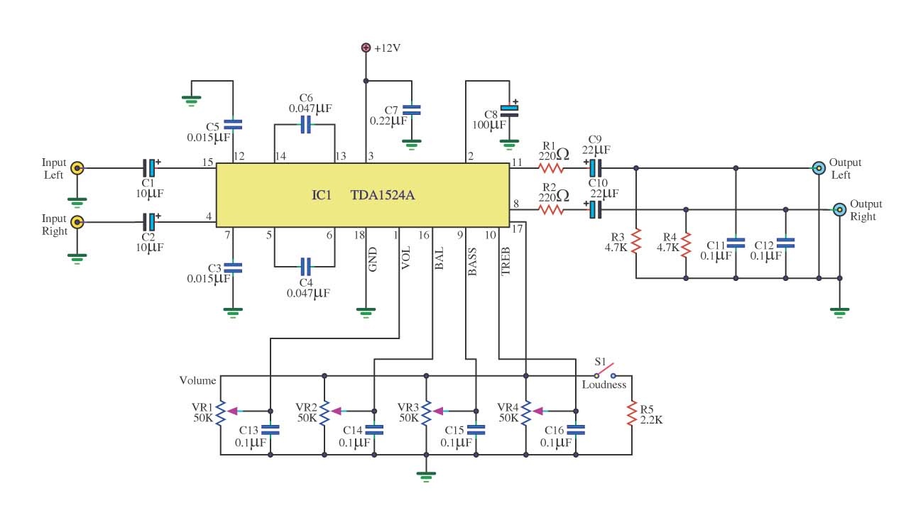
This is a simple tone control circuit using the TDA1524A, which is a key component in this IC chip diagram from Philips. The circuit allows for tone control adjustments such as bass, treble, and balance, enabling users to fine-tune...
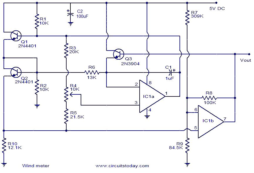
This is a simple wind meter (anemometer) circuit. While accuracy cannot be guaranteed, the circuit functions adequately. It can measure wind speeds up to 75 m/s. Transistors Q1 and Q2 are employed for wind sensing, utilizing the relationship between...
The circuit schematic is straightforward. Information regarding the assembly and testing of circuits is not provided, as there are many instructional resources available. The circuit schematic in question is designed to be simple and user-friendly, allowing for ease of understanding...
As shown in figure 14-17, this circuit consists of the input circuit, the line frequency synchronization generator, the sample-and-hold circuit, the voltage control delay generator, and the RF modulator. The input circuit includes the input attenuator RP1 and the...
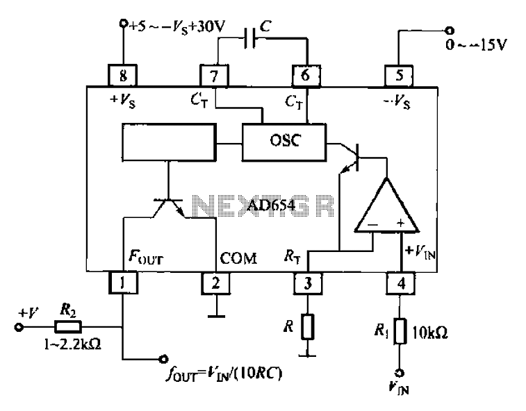
The AD654 voltage-frequency converter is a low-cost device that operates with a single supply voltage ranging from +5V to +36V, as well as with dual supplies of +5V to +18V. It can handle a maximum input voltage of 36V...

When the supply voltage drops below a minimum threshold, it is often advisable to disconnect the supply from the system to prevent poor performance or erratic operation. The circuit presented achieves this with minimal cost, board space, and complexity....
Warning: include(partials/cookie-banner.php): Failed to open stream: Permission denied in /var/www/html/nextgr/view-circuit.php on line 713
Warning: include(): Failed opening 'partials/cookie-banner.php' for inclusion (include_path='.:/usr/share/php') in /var/www/html/nextgr/view-circuit.php on line 713