
100W Medium Frequency Transmitter
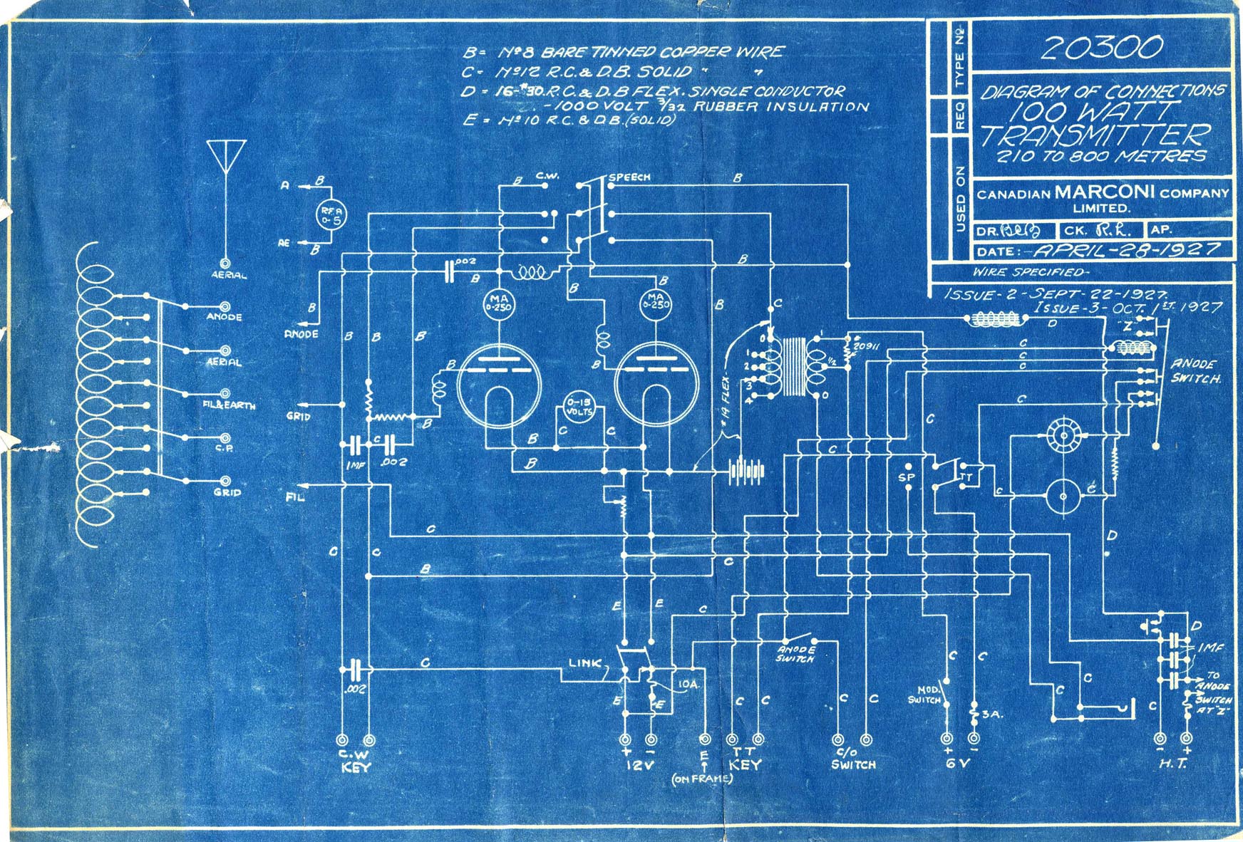
The generator consists of cumulative compound DC two armature windings. One armature winding connects to a commutator at one end of the generator, providing approximately 10-15 volts at a maximum of 12 amps (around 150 watts). The other winding connects at the opposite end of the generator to a commutator with more and finer segments, yielding a maximum output of 4 amps at 1000 volts (400 watts). There are two series fields, one in the 12-volt circuit and another in the 1000-volt circuit. A common 12-volt shunt field is included, in series with a hand-controlled field rheostat. The motor and generator are interconnected via a semi-flexible coupling.
Typically, four flexible leads extend from the wave change switch atop the transmitter to the main tuning inductance, which has a diameter of about one foot and consists of 44 turns of heavy flat copper winding. A provision for a fifth lead is included, utilized only when a counterpoise is necessary in the antenna system. For tuning to each frequency, a set of four detachable jacks is required. The taps for 425 kHz are positioned high on the coil and are less accessible than those for 500 kHz and 375 kHz. Since the wave change switch has only two positions, it is necessary to move the flexible leads from the 500 kHz taps to the 375 kHz taps when operating at 375 kHz.
The four taps for any given frequency are arranged in the following order when viewed from the back of the transmitter, from left to right: the left tap is the grid; the second is the cathode (ground); the third is the plate; and the fourth is the antenna.
1. Position the cathode tap to the left of center, ensuring sufficient turns remain between the cathode tap and the left side of the coil to accommodate the grid tap (approximately 10 turns).
2. Position the grid tap to the left of the cathode tap, leaving enough turns to guarantee adequate regeneration for oscillation (6 or 8 turns). The lower the frequency, the more grid turns will be necessary.
3. Position the plate tap to the right of the cathode tap (15 or 18 turns). The number of turns between the cathode and plate taps influences the oscillator plate current when oscillating, so it is advisable to have enough plate turns to keep the plate current below normal during initial adjustments.
4. Position the antenna tap a few turns to the right of the plate tap. The number of turns between the cathode and antenna taps determines the frequency of oscillation and radiation; more turns yield a lower frequency, and vice versa.
Once the connections to the inductance are securely established, check the wave change switch for the correct position, set the mode of operation switch to CW, close the line switch, and start the motor using the hand starter. Adjust the filament rheostat to the center of its travel, and with the filament switch closed, set the generator field rheostat so that the filament voltmeter reads 10 volts. Allow a warm-up period of 30 seconds or more for the tubes, then close the anode and aerial changeover switch, which activates the magnetic switch and applies high tension (H.T.) to the set. If the initial adjustments have been correctly performed, the transmitter should oscillate when the CW key is pressed, allowing for the observation of meter readings and frequency checks with a wave meter. An indication of antenna current when the key is pressed confirms that the set is functioning correctly.The 100W4 is a two tube medium frequency transmitter with provision for pre-tuning to three frequencies in MF band and for type A1, A2 and A3 emission. For type A1 the two tubes operate as parallel oscillators and for A2 and A3, looking at the set from the front, the left hand tube serves as a oscillator and the right hand tube as a modulator.
The oscillator is directly coupled to the antenna and antenna itself is therefore a main part of the oscillator LC circuit. With approximately 200 watts input the output is approximately 100 watts and therefore the efficiency is approximately 50%.
(slightly over 55% on CW and somewhat less on RT and TT). Generator. Cumulative compound DC two armature windings. One armature winding terminates at a commutator at one end of the generator to provide from approximately 10 - 15 volts at a maximum 12 amps approximately 150 watts. The other winding terminates at the other end of the generator at a commutator having more and finer segments than at the 12 volt end and has a maximum output of.
4 amps at 1000 volts (400 watts). There are two series fields one in the 12 volt circuit and on in the 1000 volt circuit. The generator also is provided with a common 12 volt shunt field in series with which is a hand controlled field rheostat. The motor and generator are coupled together by means of a semi flexible coupling. Normally there are four flexible leads running from the wave change switch on top of the transmitter to the main tuning inductance which is about a foot in diameter and has 44 turns of heavy flat copper winding (provision is made for a fifth lead which is only used when a counterpoise is necessary in the antenna system).
For each frequency to which the transmitter is to be tuned a set of four detachable jacks is necessary. (Taps for 425 are placed high on the coil and are less accessible then those for 500 and 375. As the wave change switch has only two positions it is necessary to move the flexible leads from the 500 Kc taps to the 375 taps when operation on 375 is required.
) The four taps for any one frequency are named in the following order when facing the transmitter from the back and reading from left to right. Left had tap grid; second cathode (ground); third plate; fourth antenna. 1 - Place cathode tap to left of center keeping in mind that enough turns must be left between the cathode tap and the left of the coil to take care of the grid tap (About 10 turns) 2 - Place grid tap to left of cathode tap enough turns so that sufficient regeneration will be assured to cause oscillation (6 or 8 turns).
The lower the frequency the more grid turns will be required. 3 - Place plate tap to right of cathode tap (15 or 18 turns). The number of turns between the cathode and plate taps determines the amount of oscillator plate current that will flow when the set is oscillating. On initial adjustments it is therefore desirable to have enough plate turns to hold the plate current to less than normal.
4 - Place antenna tap a few turns to right of plate tap. The number of turns between cathode and antenna determines the frequency of oscillation and radiation. The more turns the lower the frequency and visa versa. When connections to inductance are securely made check wave change switch for proper position, place mode of operation switch in CW position, close line switch and start motor (hand starter).
Place filament rheostat at center of travel and with filament switch closed adjust generator field rheostat so filament voltmeter read 10 volts. Allow 30 seconds or more for tubes to warm up and close anode and aerial changeover switch which closes magnetic switch and applied H.
T. to set. If initial adjustments have been properly made set should now oscillate when CW key is closed and meter readings may be observed and the frequency checked with a wave meter. A showing of antenna current when the key is pressed indicates the set is osc 🔗 External reference
Related Circuits
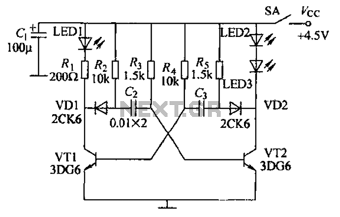
Transistors VT1, VT2, and associated RC components are configured to form a multivibrator. The multivibrator operates with resistors Ra and R4 serving as base bias resistors for VT2 and VT1, respectively. When the switch SA is closed after applying...
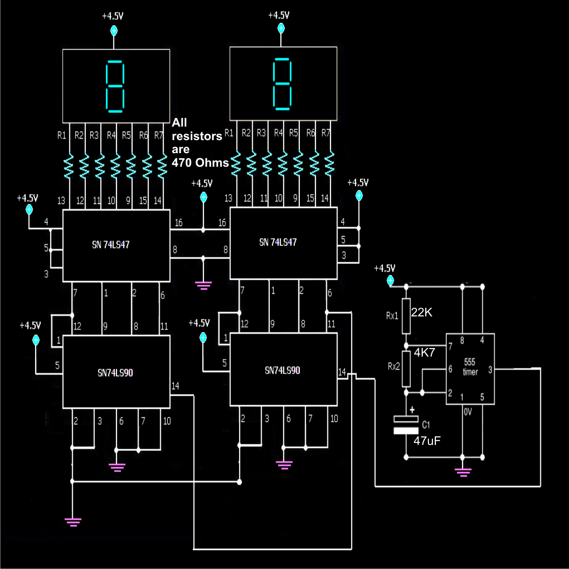
A simple frequency counter circuit can be easily constructed by any electronics enthusiast for its intended purpose. The circuit diagram was provided by Mr. Kapital through an order on Fiverr. The functioning of the circuit involves generating positive voltage...
The FM302E-I-type FM transmitter exciter is utilized in Japan's NEC HPB a 1210 motherboard. It features direct carrier frequency modulation, phase-locked frequency stabilization, and frequency synthesis. The preamplifier (BLF-177 FET) is directly driven by an actuator, achieving a maximum...
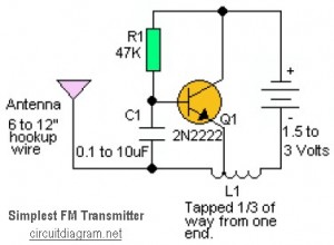
This is likely the simplest radio transmitter available. It comprises five components and can be assembled in a compact space. It is ideal for science fair projects or other science-related activities where short-range transmission is beneficial. The device operates...
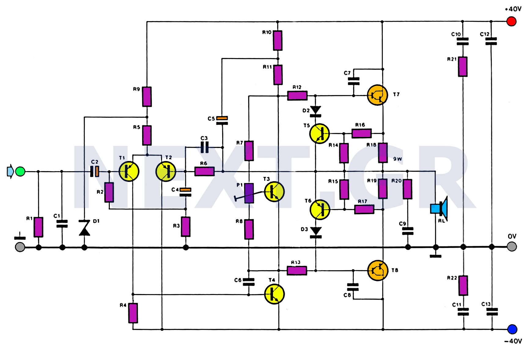
This amplifier is designed with the following specifications: distortion less than 0.1% at full power of 100W even at 20KHz, with power attributed to an extended bandwidth. The output transistors are protected against short circuits, and the power supply...
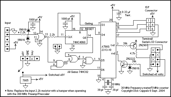
This is a design for a frequency meter based on AVR microcontrollers. Maximum input frequency is specified to be 30 MHz in the multi-chip configuration, and in single-chip configuration, there are both 5 MHz and 10 MHz versions operating...