
3000 Watt Inverter

The inverter circuit operates by utilizing a combination of power transistors or MOSFETs to switch the DC voltage on and off, generating a square wave output. The circuit typically includes a transformer to step up the voltage to the desired AC level. The square wave output is characterized by its abrupt transitions between high and low states, resulting in a duty cycle of 25%, meaning that the output is high for 25% of the time and low for 75%.
Key components of this inverter include an oscillator circuit, which generates the necessary switching signals for the transistors, and a driver circuit that amplifies these signals to drive the power transistors. The output stage may also incorporate protective features such as fuses or circuit breakers to safeguard against overload conditions.
The inverter's design must account for thermal management, as the high power output can lead to significant heat generation. Adequate heat sinks or cooling fans are often employed to maintain operational efficiency and prevent component failure.
In applications, this inverter can be used to power various devices that require AC input, making it suitable for use in off-grid power systems, emergency backup supplies, and various industrial applications. It is essential to ensure that the inverter is properly rated for the intended load and that all safety standards are met during installation and operation.This is a very-very high power Inverter circuit which will give you very high AC power output 3000W. This inverter will convert 12 Volt DC Battery voltage into a square wave voltage of 50 cycles per second and duty cycle of 25% 🔗 External reference
Related Circuits

This is a linear amplifier that requires advanced knowledge in electronics due to the complexity of the schematic diagram for a handmade circuit. It is advisable to redesign the schematic diagram using circuit design software such as DipTrace, Eagle,...
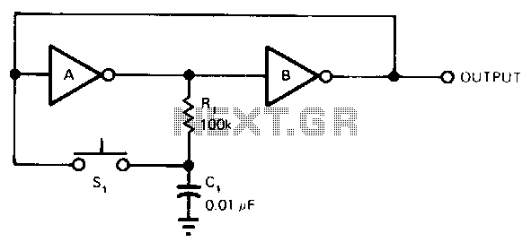
Each time the switch is closed, the voltage across capacitor C1 causes inverter A to change state, with positive feedback from inverter B. Resistor R1 delays the charging and discharging of C1, rendering the circuit nearly immune to contact...
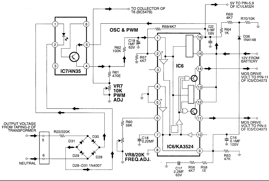
Circuit No. 1 (Oscillator Circuit and Feedback Circuit) Circuit No. 2 (MOS Driver Circuit) Final Product: - Operation of Circuit No. 1 (Oscillator Circuit and Feedback Circuit) This inverter utilizes Pulse Width Modulation (PWM) technology. The working principle of...
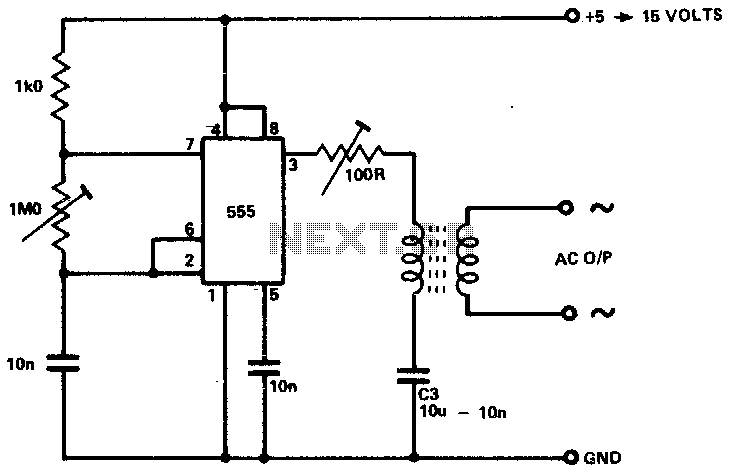
The circuit is designed to supply power for portable Geiger counters, dosimeter chargers, high resistance meters, and similar devices. The 555 timer integrated circuit (IC) operates in its multivibrator mode, with the frequency adjusted to optimize the characteristics of...
After experiencing equipment failure, a decision was made to replace a combination inverter/charger unit with individual components that fulfill the same requirements. The combination unit, referred to as the "Everything Box," is an efficient solution for cost savings by...
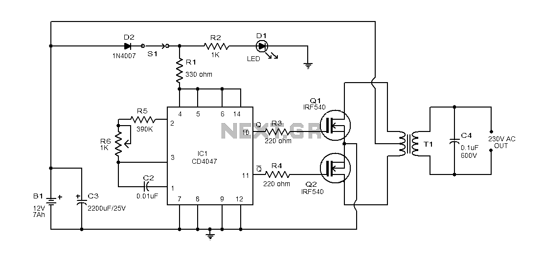
This document provides an explanation of a simple 100-watt inverter circuit using the IC CD4047 and the IRF540 MOSFET. The circuit is designed to be simple, cost-effective, and suitable for assembly on a veroboard. The CD4047 is a low-power...