
120v to 3.7v circuit
The battery circuit in question likely involves several key components that are essential for proper functionality. Typically, such circuits include a battery, a charging module, and various protection elements to ensure safe operation. The salvaging process may involve reusing components such as resistors, capacitors, or integrated circuits that were previously part of a functioning system.
When integrating a salvaged circuit with a new battery, it is crucial to ensure compatibility in voltage and current ratings to prevent damage. The circuit should also include a method for monitoring the battery's state of charge, which can be accomplished through voltage dividers or dedicated battery management ICs.
Protection features, such as overcurrent protection, overvoltage protection, and thermal management, are vital to enhance the reliability and safety of the battery circuit. These can be implemented using MOSFETs, fuses, and thermistors, respectively.
Additionally, the layout of the circuit board should be carefully designed to minimize resistance and inductance, which can affect performance. Proper grounding techniques and the use of decoupling capacitors can help mitigate noise and ensure stable operation of the circuit.
In summary, salvaging a battery circuit and integrating it with a new battery requires careful consideration of component compatibility, safety features, and circuit design principles to achieve a reliable and efficient power supply solution.Oh, one thing I forgot to mention about the battery ""circuit"" I attempted to salvage the circuit and put it inline with the new battery,.. 🔗 External reference
Related Circuits
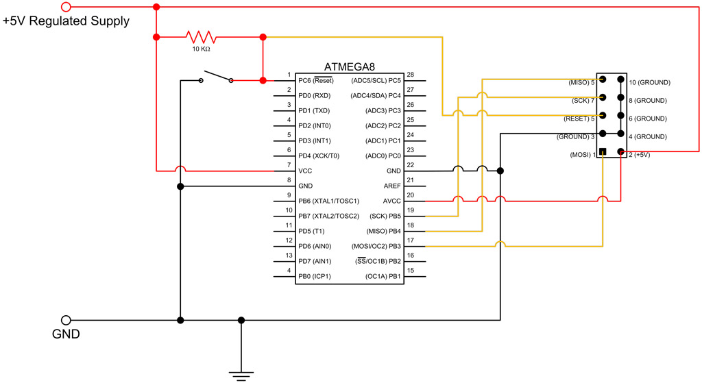
This tutorial continues from the ATmega8 Breadboard Circuit Part 1, where a small power supply was built on a breadboard. In this part, the ATmega8 microcontroller will be added along with an interface for programming. The first step is...
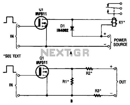
The hexFET can switch DC power to relays, motors, lamps, and various other devices. This configuration can also be utilized to switch resistors in and out of a circuit. R1, R2, and R3 represent resistive loads that can be...
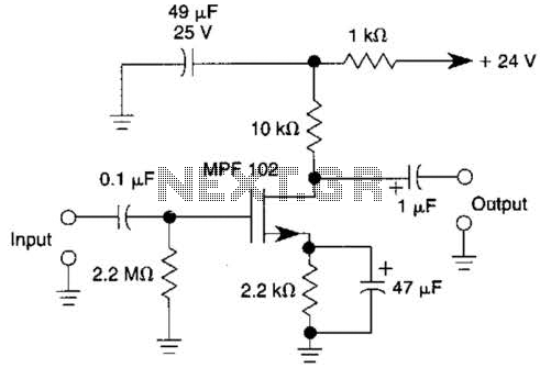
This JFET preamplifier has a gain of approximately 20 dB and a bandwidth exceeding 100 kHz. It is useful as a low-level audio amplifier for high-impedance sources. The described JFET (Junction Field Effect Transistor) preamplifier is designed to amplify low-level...
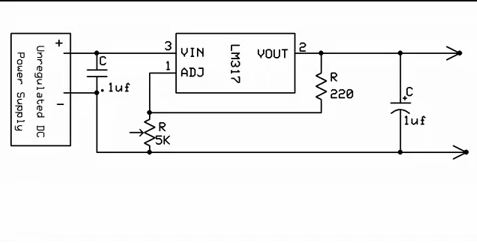
A simple method for charging a battery from a higher voltage battery is illustrated in the circuit below on the left. Only one resistor is required to establish the desired charging current, which is determined by dividing the difference...
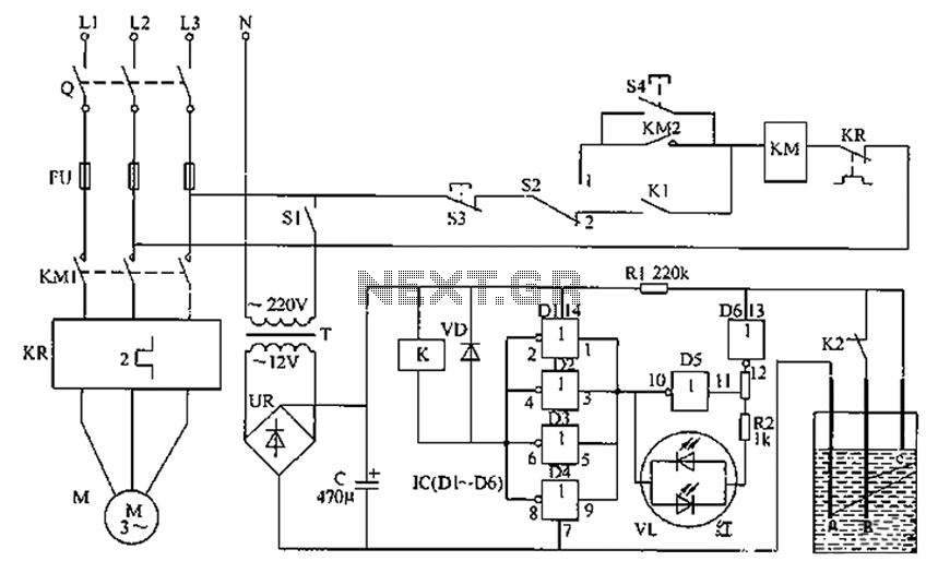
The liquid level automatic controller circuit consists of a power circuit, a control instruction level detection circuit, and a starter control circuit. The power circuit is formed by a power transformer, a rectifier bridge, and a filter capacitor. The...
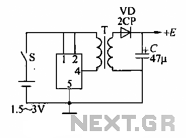
A DC booster circuit is illustrated in the figure, which represents a step-up transformer circuit diagram. The step-up transformer (T) can be utilized to power small transistor radios. The winding ratio can be adjusted to achieve the desired output...
Warning: include(partials/cookie-banner.php): Failed to open stream: Permission denied in /var/www/html/nextgr/view-circuit.php on line 713
Warning: include(): Failed opening 'partials/cookie-banner.php' for inclusion (include_path='.:/usr/share/php') in /var/www/html/nextgr/view-circuit.php on line 713