
12v high/low battery monitor

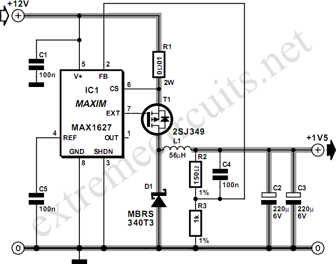
The circuit described employs a resistor (R1) to set a specific voltage threshold known as the trip-point. This trip-point is crucial for determining when the circuit will activate or deactivate a connected load, such as an LED. The adjustment of R1 allows for calibration of this threshold, enabling the user to fine-tune the circuit's sensitivity to the input voltage, which in this case is derived from a battery.
To modify the logic of the circuit so that the LED illuminates when the battery voltage exceeds a specified level (X), the LED should be connected to ground through another resistor, R4. This configuration creates a condition where the LED will turn on when the voltage across R4 is sufficient to forward bias the LED, indicating that the battery voltage is above the desired trip-point.
Both R1 and R4 are specified to have tolerances of 5% or 10%, ensuring that the circuit maintains a degree of reliability and predictability in its operation. The power rating of 1/4-watt for these resistors suggests that they are suitable for low-power applications, which is typical in battery-operated devices.
In summary, the combination of R1 for trip-point adjustment and R4 for LED control provides a fundamental mechanism for monitoring battery voltage levels, with the potential for user-defined thresholds and clear visual feedback through LED illumination.R1 controls the trip-point of the circuit. adjust it accordingly. to reverse the logic (have the led light up when the battery has at least X amount of power,) connect the led to ground through R4. all resistors are 5 or 10 percent tolerance, 1/4-watt 🔗 External reference
Related Circuits

This 555 timer circuit temperature monitoring system project can monitor temperature at up to four points. The system allows for the selection of whether the alarm should be triggered when the temperature increases or decreases, depending on the resistance...
Most small internal combustion engines commonly used in model building utilize glow plugs for starting. However, glow plugs operate at a voltage of 1.5 V, while components such as fuel pumps, starter motors, and chargers typically operate at 12...
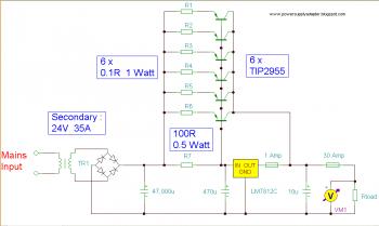
The charger's output voltage is adjustable and regulated, featuring an adjustable constant-current charging circuit that is compatible with most NiCad batteries. It is capable of charging a single cell or multiple series-connected cells with a maximum voltage of 18V....
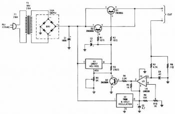
The input transformer is likely to be the most expensive component of the entire project. Alternatively, a pair of 12 Volt car batteries could be utilized. The input voltage to the regulator must be several volts higher than the...
The following circuit illustrates an Elektroblock circuit diagram utilizing a 12V power supply. Features include various control and monitoring functions, with the specification of an 18 A LAS 1218 component. The Elektroblock circuit is designed to operate with a 12V...
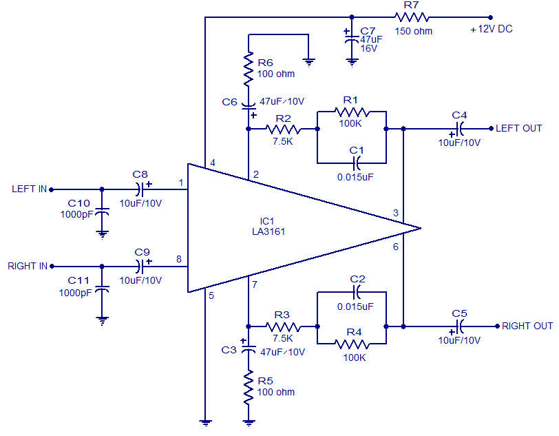
The LA3161 is an integrated two-channel preamplifier designed for car stereo applications. It operates on a 12V DC power supply. The LA3161 preamplifier is specifically engineered to enhance audio signals in automotive environments, ensuring optimal sound quality for car stereo...