
12V Powered 12V Lead Acid Battery Charger with Indicator
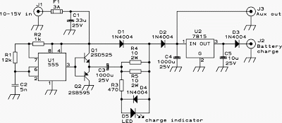
The described charger circuit is a practical solution for charging small lead-acid batteries from a vehicle's electrical system. The capacitive voltage doubler stage is critical for stepping up the voltage to the required level, ensuring that the charging process is efficient and controlled. The 555 timer IC plays a pivotal role in managing the timing and operation of the transistors, which are configured to provide stable output while minimizing losses. The use of emitter followers helps in maintaining a low output impedance, which is beneficial for driving the voltage doubler effectively.
The 7815 voltage regulator IC is a reliable choice for maintaining a consistent output voltage. Its integration into the circuit ensures that the battery receives the appropriate voltage for charging without exceeding safe limits. The addition of a diode in the output path is essential for protecting the circuit from reverse current, which could otherwise damage the charger.
The inclusion of a charge indicator LED enhances usability by providing visual feedback on the charging status. This feature is particularly useful for users to monitor the charging process without needing to measure current or voltage directly. The auxiliary output is a versatile feature, allowing for charging of different battery types, which expands the utility of the charger beyond just lead-acid batteries.
The thermal management aspect of the design is crucial, especially given the potential for heat generation in the regulator IC. Mounting the IC and transistors to the aluminum enclosure not only provides a heat sink but also contributes to the overall durability of the charger. The design emphasizes safety through the use of fuses and protective diodes, ensuring that users can operate the charger with confidence.
Overall, this charger design represents a robust and straightforward solution for maintaining small lead-acid batteries, suitable for both casual users and those with a technical background looking to build their own charging solution.Some of you might wonder why a charger is needed at all, to charge a 12 Volt battery from a 12 Volt source! Well, firstly the "12 Volt" source will typically vary anywhere from 11 Volt to 15 Volt, and then a battery needs a controlled charge current and voltage, which cannot result from connecting it directly to a voltage source.
The charger descr ibed here is intended for charging small 12 Volt lead acid batteries, such as the gelled or AGM batteries of capacities between about 2 and 10 Ah, using a cars electrical system as power source, regardless of whether the car engine is running or not. I built this charger many years ago, I think I was still in school back then. On request of a reader of my web site, Im publishing it now, despite being a rather crude circuit. It works, it is uncritical to build, and uses only easy-to-find parts, so it has something in its favor.
The downside is mainly the low efficiency: This charger wastes about as much power as it puts into the battery. The charger consists of two stages: The first is a capacitive voltage doubler, which uses a 555 timer IC driving a pair of transistors connected as emitter followers, which in turn drive the voltage doubler proper.
The doubler has power resistors built in, which limit the charging current. The second stage is a voltage regulator, using a 7815 regulator IC. Its output is applied to the battery via a diode, which prevents reverse current and also lowers the voltage a bit. The resulting charge voltage is about 14. 4V, which is fine for charging a gelled or AGM battery to full charge, but is too high as a trickle charger, so dont leave this charger permanently connected to a battery.
If you would like to do just that, then add a second diode in series with D3! There is a LED connected as a charge indicator. It will light when the charge current is higher than about 150mA. The maximum charge current will be roughly 400mA. There is an auxiliary output, that provides about 20V at no load (depending on input voltage), and comes down as the load increases. I included this for charging 12V, 4Ah NiCd packs, which require just a limited current but not a limited voltage for charging.
Note that if the charge output is short-circuited, the overcurrent protection of U2 will kick in, but the current is still high enough to damage the diodes, if it lasts. So, dont short the output! If instead you short the auxiliary output, the fuse should blow. I built this charger into a little homemade aluminum sheet enclosure, using dead-bug construction style.
Not very tidy, but it works. Note the long leads on the power resistors. They are necessary, because with shorter leads the resistors will unsolder themselves, as they get pretty hot! The transistors and the regulator IC are bolted to the case, which serves as heat sink. The transistors dont heat up very much, but the IC does. 🔗 External reference
Related Circuits
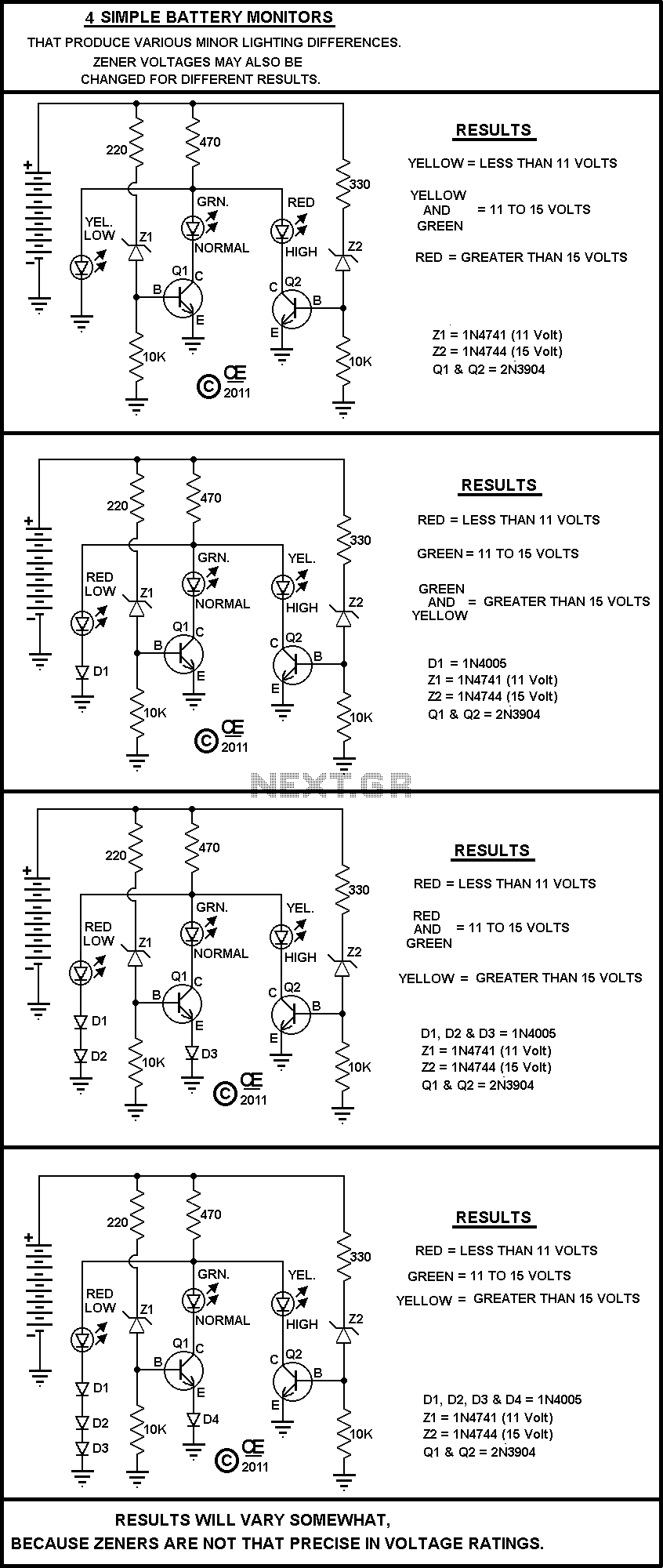
This circuit is used to measure the voltage on a 12V (nominal) lead acid rechargeable battery system. It was specifically designed for use in solar powered systems, but is general enough that it can be used for automotive or...
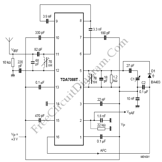
The TDA7088T can be used in mono portable and pocket radios. This is a bipolar integrated circuit. Here is one of the application circuit diagrams. The TDA7088T is a versatile bipolar integrated circuit designed specifically for mono FM radio applications,...
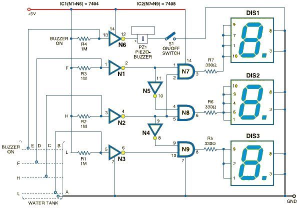
This schematic outlines a straightforward electronic project for designing a water level indicator circuit. It employs a 7-segment display to represent water levels in a tank as low, half, and full, indicated by the letters L, H, and F,...
A Very Simple circuit and some Variations. Play with it. All parts are cheap and should be easily obtained. None are very critical. The circuit in question is a basic electronic assembly designed for educational purposes and experimentation. It typically consists...
This circuit defines seven levels in a reservoir. The sensed values are connected to an encoder circuit, which consists of a 74148 integrated circuit (IC), functioning as an 8-line to 3-line encoder. The next section features a HEX display,...
Most small internal combustion engines commonly used in model building utilize glow plugs for starting. However, glow plugs operate at a voltage of 1.5 V, while components such as fuel pumps, starter motors, and chargers typically operate at 12...