
135-175Mhz amplifier

The circuit utilizes ARCO #462 trimmer capacitors, which provide a capacitance range of 2 to 60 picofarads (pF). These capacitors are essential for fine-tuning frequency responses in RF applications. The capacitors are denoted as C2 in the schematic, indicating their specific role in the circuit.
The inductors, represented as L1 and L2, are constructed using #20 AWG wire. L1 features three turns of wire wound around a 1/4-inch diameter form, which contributes to its inductive properties. The choice of wire gauge and the number of turns are critical parameters that influence the inductance value, affecting the overall circuit performance.
L2 is similarly wound with the same gauge wire, but the exact number of turns is represented as β, indicating a variable or unspecified number of turns based on the design requirements. The diameter of the inductor forms is consistent, ensuring uniformity in the inductive behavior across the circuit.
Additionally, the circuit includes a 25 Ω coaxial cable wound in a single turn around two balun cores. This configuration is likely employed to facilitate impedance matching and signal transformation between different circuit sections, optimizing power transfer and minimizing signal loss. The use of coaxial cable is advantageous for reducing electromagnetic interference (EMI) and maintaining signal integrity in high-frequency applications.
Overall, this circuit design incorporates essential RF components, including trimmer capacitors and inductors, to achieve precise tuning and effective signal management in its intended application.Cl. C2 ARCO #462,2 to 60 pF, trimmer capacitors Li, 3 turns byss wire #20 AWG on 1/4" diameter L2, ß turns *20 AWG on 114" diameter Ti 1 turn of 25 O coax on 2 balun cores.
Related Circuits
A 1000 Watts audio power amplifier circuit designed for outdoor use. A circuit diagram is needed urgently to facilitate the construction of this high-power amplifier, which is a personal passion project. The design of a 1000 Watts audio power amplifier...
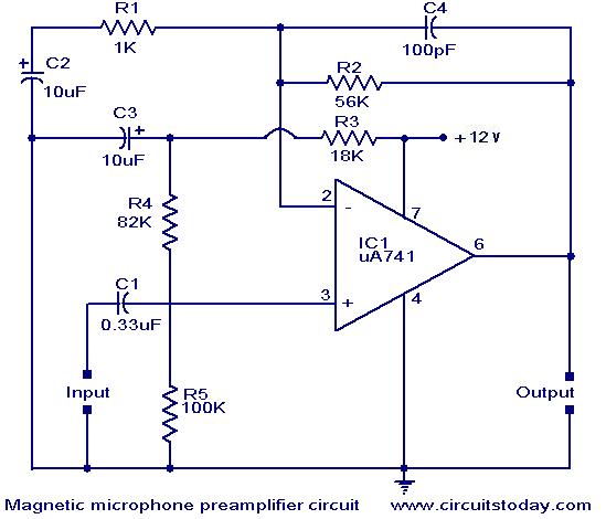
A preamplifier for magnetic pickups of record players is presented. The uA 741 is utilized as an AC-coupled non-inverting amplifier operating on a single supply. The amplifier gain is determined by the feedback components, where C2 manages the low-frequency...
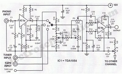
This Hi-Fi stereo preamplifier circuit is constructed using the TDA1054 integrated circuit (IC) from SGS. The TDA1054 is housed in a 16-pin DIL package and incorporates two separate preamplifier circuits. It is characterized by low noise and minimal issues...
Both transistors should be low noise types. In the original circuit, BC650C was used, which is an ultra-low noise device. These transistors are now hard to find, but BC549C or BC109C are good replacements. The circuit is self-biasing and...
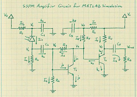
The silicon photomultipliers (SiPM) utilized in the experiment were acquired from Photonique, which also provides analog electronics boards to amplify the signals from the SiPMs. This document addresses the analysis and modeling of the amplifier circuit, along with the...
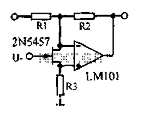
A 1.53 voltage-controlled gain amplifier (VGA) utilizes a FET connected between the two inputs of the operational amplifier (op-amp) as a voltage-controlled resistance. The resistance changes linearly with voltage and varies from several dozen square ohms, exhibiting excellent control...