
14V Switching Power Supply
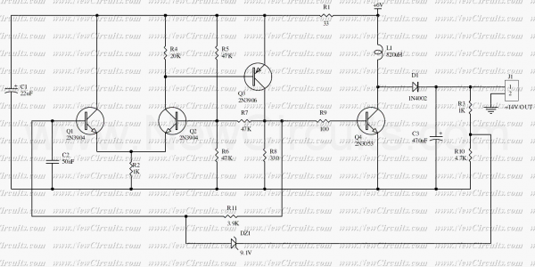
The described circuit operates as a basic switching power supply utilizing a Schmitt trigger oscillator. The oscillator is responsible for generating a square wave signal that drives a switching transistor, typically a MOSFET or bipolar junction transistor (BJT). When the transistor is in the 'on' state, current flows through the inductor, allowing it to store energy in the form of a magnetic field. The inductor's ability to store energy is a fundamental aspect of the circuit's operation, as it provides the necessary energy transfer to the load when the transistor switches off.
Upon transitioning to the 'off' state, the energy stored in the inductor is released into the load circuit. This transition is critical, as it enables the circuit to deliver a regulated output voltage. The output voltage is influenced by the load resistance; as the load changes, the voltage will vary accordingly.
To maintain a stable output voltage, a zener diode is incorporated into the circuit. The zener diode serves as a voltage clamp, preventing the output voltage from exceeding a predetermined level, in this case, approximately 14 volts. When the output voltage reaches this threshold, the zener diode becomes forward-biased, effectively stopping the oscillator and thus ceasing the operation of the switching transistor.
For applications requiring different output voltages, the circuit can be adjusted using a voltage divider that feeds into the zener diode. By modifying the resistor values in the voltage divider, the reference voltage can be altered, allowing for a range of output voltages to be achieved. This adjustability makes the circuit versatile for various applications where different voltage levels are needed.
Overall, this small switching power supply is a practical solution for efficiently converting and regulating voltage, leveraging the principles of inductive energy storage and feedback control through the use of a Schmitt trigger oscillator and a zener diode.In this small switching power supply, a Schmitt trigger oscillator is used to drive a switching transistor that supplies current to a small inductor. Energy is stored in the inductor while the transistor is on, and released into the load circuit when the transistor switches off.
The output voltage is dependent on the load resistance and is limited by a zener diode that stops the oscillator when the voltage reaches about 14 volts. Higher or lower voltages can be obtained by adjusting the voltage divider that feeds the zener diode.
🔗 External reference
Related Circuits
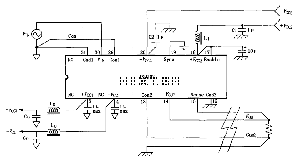
The basic connection circuit for the ISO107 signal and power supply is illustrated. Each power supply terminal must include a bypass filter. If the output current from the isolated power supply exceeds 15 mA, it is advisable to utilize...
These are small lights with a stake on the bottom that can be inserted into the ground along driveways or sidewalks, featuring a solar panel on top. The solar cell charges a AA NiCd battery during the day, and...
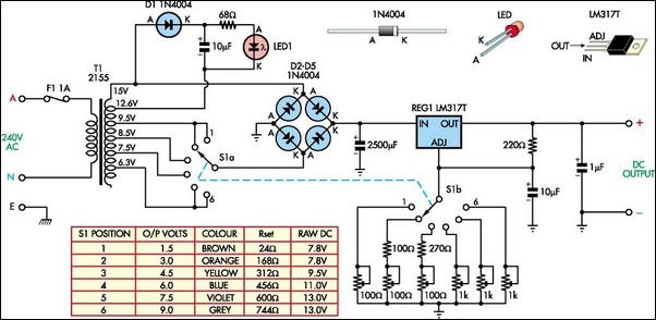
The following circuit illustrates a Battery Replacement Power Supply Circuit Diagram. This circuit is based on the LM317 integrated circuit. Features include the ability to replace... The Battery Replacement Power Supply Circuit utilizes the LM317 voltage regulator to provide a...
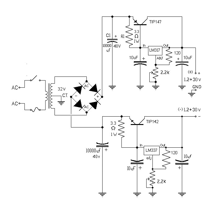
The 10A variable power supply circuit is symmetrical and can provide a symmetrical output voltage ranging from ±1.2 volts to ±30 volts DC, with a maximum current of 10A. This circuit utilizes symmetrical variable voltage regulators LM317 and LM337,...
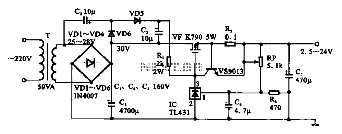
An adjustable DC power supply circuit is presented, consisting of a step-down transformer (T), a rectifier bridge (VD1 to VD4), and additional components. The voltage regulator circuit includes an adjustment potentiometer (RP, 5.1 kΩ), allowing the output voltage to...
This power supply was designed for use with the Simple hybrid amplifier published elsewhere in this issue. It is suitable for various applications. A cascade generator is employed for the 170 V output, a switch mode supply for the...