
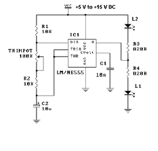
15hz zapper schematic

The schematic represents a 15Hz zapper circuit, which is designed to deliver electrical pulses at a frequency of 15 Hz. This type of device is often utilized for various therapeutic applications, including pain relief and muscle stimulation.
The circuit typically consists of several key components: a microcontroller or oscillator to generate the desired frequency, resistors to limit current, capacitors for timing and stability, and a transformer or output stage to deliver the pulses to the electrodes.
1. **Oscillator**: The oscillator is the heart of the circuit, generating a square wave output at 15 Hz. This can be achieved using a 555 timer IC configured in astable mode or a microcontroller programmed to produce the desired frequency.
2. **Resistors**: Resistors are used to set the timing characteristics of the oscillator and to limit the current flowing through the circuit. Proper selection of resistor values is crucial to ensure that the output signal remains within safe and effective limits.
3. **Capacitors**: Capacitors are employed to filter the output signal and stabilize the frequency. They also play a role in coupling the signal to the output stage, ensuring that the pulses are delivered effectively to the load.
4. **Output Stage**: The output stage may include a transformer or an operational amplifier configured to provide the necessary voltage and current levels to the electrodes. This stage is essential for ensuring that the pulses can penetrate the skin effectively and reach the target tissues.
5. **Electrodes**: The circuit interfaces with the user through electrodes, which are placed on the skin. The design should ensure that the electrodes are safe to use and provide good contact with the skin to facilitate effective treatment.
Overall, the design of a 15Hz zapper circuit requires careful consideration of component values and circuit topology to achieve the desired therapeutic effects while maintaining user safety. Proper testing and validation of the circuit are also essential to ensure reliability and effectiveness in its application.A simple schematic detailing a 15Hz zapper with correct component values.. 🔗 External reference
Related Circuits
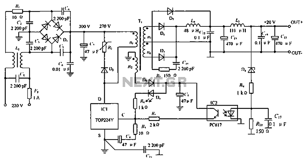
The circuit depicted in the figure is designed to achieve a higher power output by modifying specific components. On the left side of the figure, components R1, L1, D1, and capacitors C1 to C7 form a conventional filtering and...
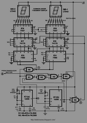
This circuit is designed to display the speed of a vehicle in kilometers per hour (km/h). An opaque disc is mounted on the spindle connected to the front wheel of the vehicle. The disc features evenly spaced holes along...
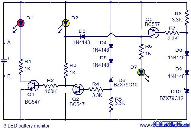
This is the circuit diagram of a 3 LED bar graph type battery monitor circuit that is ideal for monitoring the voltage level of an automobile battery. When battery voltage is 11.5V or less, transistor Q1 will be on...
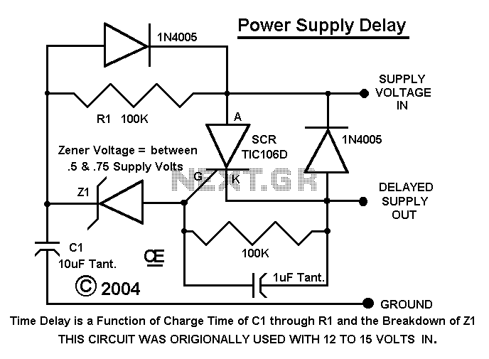
I had designed up an oscillator with a Power Output circuit. Problem was when power was applied to the entire circuit, the output of the Oscillator gave a Momentary Spike into the output circuit. Thus Driving it full on...
This is a simple LED flasher project that utilizes a common 555 timer integrated circuit (IC) for its operation. It is configured in astable mode, which means its output functions as a square wave oscillator. Two LEDs are connected...
For a candle to burn, we need a heat source (the flame of a match) and to extinguish it, you do it just to blow out. The following circuit behaves similarly. If you use your fingers heats the thermistor,...