
Most Accurate Clock

The three-channel HF receiver is designed to operate within the specified frequency ranges, equipped with a disciplined 3.6 MHz crystal oscillator to maintain accurate time synchronization. The architecture includes a radio frequency (RF) front end, intermediate frequency (IF) processing, and a microcontroller for decoding and displaying time information. The RF front end captures signals via the whip antenna and amplifies them using low-noise amplifiers (LNAs). The signals are then down-converted to an intermediate frequency through a mixer circuit, which utilizes the local oscillator (LO) signals generated by the crystal oscillators.
The microcontroller processes the demodulated signals and extracts the time code data, which is displayed on a digital readout. This process involves filtering and decoding the amplitude-modulated signals to ensure accurate timekeeping. The circuitry also incorporates phase-locked loop (PLL) technology to stabilize the frequency output and maintain synchronization with the WWV or WWVH broadcasts.
The design includes a user interface with operational controls for tuning and calibrating the receiver, allowing for adjustments to the tone board and ensuring optimal performance across the frequency channels. The receiver's sensitivity and selectivity are critical parameters, influenced by the design of the IF filters and the gain settings of the amplifiers. The performance is further enhanced by careful alignment of the LO frequencies, ensuring that they remain within the desired bandwidth for effective signal capture.
In summary, the three-channel HF receiver is a sophisticated device that integrates RF technology with digital processing to provide precise timekeeping capabilities, leveraging historical techniques while incorporating modern advancements in electronics.I built one of these with the RS-232 option many decades ago. It a three channel HF receiver (5, 10 & 15 MHz) that receives either the U. S. or Hawaii WWVH time and frequency broadcasts and displays the time to a tenth of a second. It also has a discipline function that tweaks a 3. 6 MHz crystal oscillator. So it could be called an HFDO, which was available decades prior to any GPSDO like the Thunderbolt or Stanford Research PRS-10. The PST 1020 is a newer WWV/WWVH clock which is faster to acquire the time. In the photo at the top of the page the clock has just been powered up and is searching for the signal using only the 53" whip antenna. When the speaker is turned on you can hear the signal but the clock is not capturing the data stream.
Maybe the signal is too weak, or the receiver needs to be aligned It`s also possible that the "8" digits are an artifact of the camera exposure. Using the HP 8648A signal generator, with the 1E2 modulation option, it`s possible to generate an RF signal at 5, 10, or 20 MHz with either 100 or 1000 Hz modulation (and a choice of sine, square and other 100% AM waveforms).
There is an audio file that could be used to AM modulate the signal generator and should cause the clock to display the encoded time. A better way would be to have a PIC micro controller clock that outputs the 100 & 1000 time code data as audio to feed the AM input of the sig gen.
Guessing that the problem might be: (1) crystal that`s not too active or (2) a weak Q305 (2N5770) transistor, (3) too close to the bandwidth of the scope or some combination of these. BUT. . after returning them to the original locations testing at 5 MHz showed the yellow data LED will light with 100 Hz modulation and the capture LED with 1 kHz modulation.
But after trying 10 Mhz, no luck on either 100 or 1000 Hz modulation, and coming back to 5 Mhz now only the 100 Hz tone decoder is working. At 5 Mhz after re-capping the red AM LED is off at -132 dBm and on solid at -120 dBm (in TEST mode). This required a slight tweak of the 1000 Hz pot. This may be a better way to set the tone board pots than using the internal calibration which probably has a strong audio signal.
Note: the green Capture LED has a very long time constant. It takes 12 seconds after applying -110 dBm @ 5 MHz to turn on, and 12 seconds to turn off after the RF is turned off. At 10 Mhz after re-capping it takes 15 seconds for the green Capture LED to turn on after applying -100 dBm andjsut a few seconds to turn off.
But the turn off time seems to vary between a few seconds and almost a minute. At 15 Mhz after re-capping it takes -90 dBm to get the red AM light to come on in TEST mode. BUT, after switching to normal mode the green Capture LED does not turn on. It looks like the LO crystals for 10 & 15 Mhz are not centering the signal in the IF passband. This may mean that it matters which channel is used to tweak the tone board pots. For now I`ll leave it with the 5 MHz channel well centered since that`s the channel that works best at night. The total IF bandwidth should be the same for all the channels. That it`s not indicates that my method of using a low flash rate for the yellow LED could be inproved.
After some discussion about the loading caps for the three LO crystals I checked my GC-1000 LO frequenices by connecting the antenna and one of the rear panel BNC connectors ground to the 4395A in spectrum analyzer mode. As long as the LO keeps the WWV carrier and sidebands inside the IF bandwidth it should not matter. The tone frequency that`s output will depend only on the AM input signals. Since the bandwidth of the 100 Hz PLL is narrow it may be that using the built-in tone generator for tuning is a mistake.
It may be better to use a signal generator or an off the air signal to peak the tone board decoders. I think the micro controller is the Mostek MK3870/22, i. e. it has 2048 bytes of ROM and 64 bytes of RAM. The / 🔗 External reference
Related Circuits

The thermostat electric circuit operates as depicted in the figure. It has three settings: off, low power (Lo), and high power (Peru HL). When the DIP switch SA is set to the Lo position, 220V AC is directed through...

The term "mixed-signal" typically refers to circuits and integrated circuits (ICs) that process both analog and digital signals. In this context, the designation "A mixed-signal LED clock" may be somewhat misleading, as this is a fully digital clock. However,...
TI's Dafydd Roche concludes his 4-part series on soundbar design with a thorough explanation of clock design for the digital section of the circuit. The clock design in digital circuits, particularly in soundbar applications, plays a crucial role in ensuring...
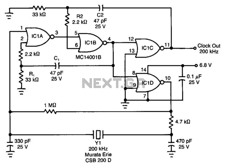
Ceramic resonators are suitable for low-power, low-frequency clock sources, despite their 30-ppm temperature coefficient. However, they exhibit troublesome spurious-resonance modes. This circuit effectively rejects all but the fundamental mode of the resonator. The clock circuit operates within a temperature...
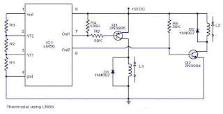
The values of the LM56 thermostat project circuit diagram for resistors R1, R2, and R3 at the travel points VT1 and VT2 can be determined using the following equations. This electronic circuit thermostat with the IC LM56 serves as...
Excellent clock generator to drive 4017 type cmos circuits. R1 = 10K to 10M, C1 = 100pF to 47uF. Fo is ±1Kz when R1=100K and C1=10nF. Input voltage can be from 5 to 15V. The described clock generator circuit is...